
The following video demonstrates the direct test method for ensuring proper functionality of your PCR, PCRH, PCRX, or SSD.
For more detailed information, visit our direct testing knowledge base article.
The ISP is Dairyland’s original solid-state AC conducting/DC blocking device designed for the corrosion prevention industry in 1990. Of all Dairyland’s decouplers, the ISP—which stands for Isolator/Surge Protector—provides the widest range of features and ratings. This includes the highest levels of AC fault-handling capability – up to the highest typical transmission system faults, which makes the ISP the preferred product for power utility underground cable decoupling/bonding requirements.
The ISP is typically connected between the casing of a power utility pipe-type transmission cable system and the substation grounding system. Here, the ISP provides DC isolation and AC coupling to the grounding system of the substation.
This article will cover what an ISP is and how an ISP functions during different field conditions that include steady-state, AC faults and lightning faults. In addition, a brief explanation on how to test ISP’s in-circuit and the benefits of testing ISP’s using Dairyland’s automated ISP tester.
What is an ISP?
Dairyland’s ISP includes the following components: a capacitor circuit for steady-state operation, thyristors T1 and T2 rated for high fault current handling, a logic control circuit for switching operation, and a surge protector circuit for lightning and fast transient events. The two-terminal device has a blocking threshold voltage of 12.5V or 20V, in which it will block DC current if the voltage threshold is not exceeded. Once the threshold voltage is exceeded, the ISP transitions into a low-impedance state within 4ms, effectively becoming a virtual short circuit that safely conducts AC and DC fault or surge currents to ground, limiting system voltage rise. Reference simplified ISP circuit below in Figure 1.
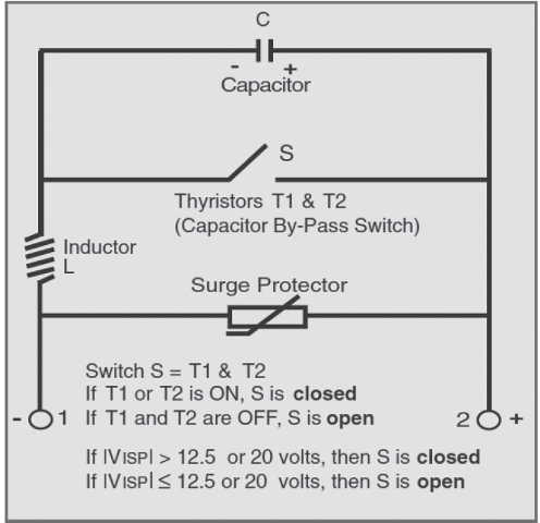
Figure 1: Simplified Circuit of an ISP
Functions of an ISP
Steady-State AC Operation
As seen in Figure 2 below, under normal operating conditions, when AC voltage is applied to the ISP, current flows through the inductor (L) and capacitor (C), supporting continuous conduction up to the selected steady-state AC current rating. The switch (S) and surge protection circuit remain open, and no current flows through them.
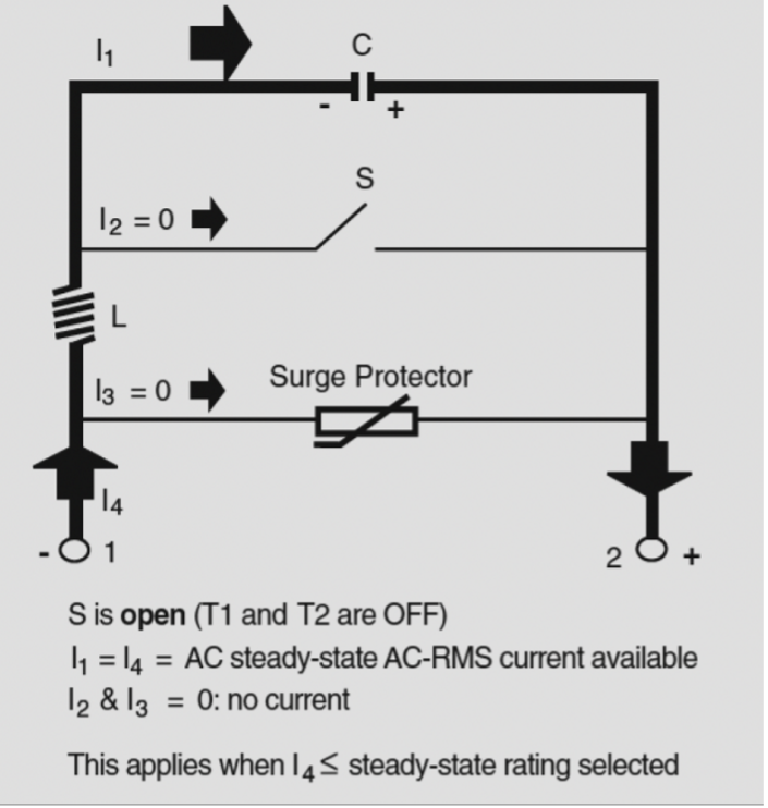
Figure 2: Steady-State AC Current Flow
AC fault current operation
The ISP is designed to withstand currents above its steady-state AC current rating, which means that during AC faults, it is protected against failure, however it no longer blocks DC. Whenever the device operates beyond its steady-state AC current limit or the DC voltage exceeds the switching threshold, a red indicator on the ISP cover flashes intermittently as a warning.
As shown in Figure 3, during an AC fault, the predominant current flow path moves through switch S1 (S) with minimal current flow through the capacitor (C). During this time, the capacitor (C) is protected from excessive current and voltage. There is no current flow through the surge protection path.
Dairyland ISPs are rated for 35kA, 68kA or 118kA, 1 cycle at 60Hz. Some older models remain in operation as well in 7kA and 24kA ratings.
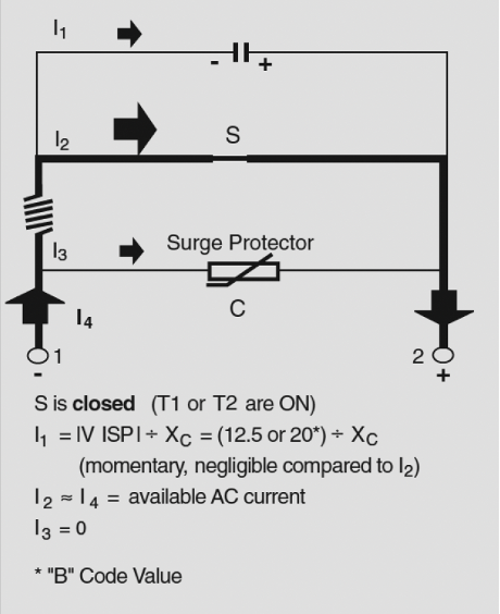
Figure 3: Current Path During AC Faults
Lightning and transient event operation
Under lightning (or switching transient) surge conditions, where the input current has a very fast rise time, the conduction path through the ISP is different than for AC conditions.
Please note Figure 4 below. When the ISP is exposed to a lightning surge, the voltage developed across the inductor (L) instantly rises to a value that places the surge protector (metal oxide varistor) into conduction, enabling the surge protector to carry the bulk of the current. Since the peak voltage across the thyristor also rapidly exceeds the threshold level, switch S is also put into conduction. However, the impedance of the current path through the thyristor is now much higher because the inductor is in series with this path. The impedance of the inductor allows only a small fraction of the surge current through the ISP to be carried by the thyristors, thereby preventing failure of the thyristors due to excessive rate of change of current. Most of the current will travel along the lower impedance path through the surge protector.
ISPs are rated for 75kA (standard) or 100kA (optional) 8x20ms waveform.

Figure 4: Current Path During Lightning Faults
Testing an ISP in-circuit
This test is completed with the device connected in-circuit — no terminal disconnections needed. Please note: this test only checks for internal shorts and not logic control circuit functions.
Refer to and follow company safety procedures prior to testing.
Equipment Required
- A multimeter with AC/DC amperes, volts, ohms.
- A clamp-on AC/DC ammeter
The ISP should be completely silent (noise-free). If an audible clicking sound is heard, the ISP is being subject to an AC current that is above its rating for the DC voltage applied. This sound is caused by a magnetic effect of certain solid-state components and is not any form of electrical arcing. In addition, a red indicator on the cover of the ISP will flash intermittently.
To verify that the ISP is functioning properly, first measure the AC voltage across the terminals using the DMM. Second, measure the AC current flowing through the negative terminal. Finally, calculate the impedance, Vac/Iac. These values should be approximately equal. Refer to the impedance table in this article and the nameplate of the ISP to determine the correct value to compare to.
Example1:
- Vac measured across terminals = 1V
- Iac measured with clamp-on = 10A
- Impedance Calculated = 1V / 10A = 0.1Ω
- For ISP with 90A rating, Published Impedance = 0.09Ω
- Values agree = Unit passes
Example 2:
- Vac measured across terminals = 0.1V
- Iac measured with clamp-on = 10A
- Impedance Calculated = 0.1V / 10A = 0.01 Ω
- For ISP with 90A rating, Published Impedance = 0.09Ω
- Values disagree = Unit fails test
- Unit is actively conducting or failed shorted.
- LED flashing if conducting (if present)
Testing with ISP Tester
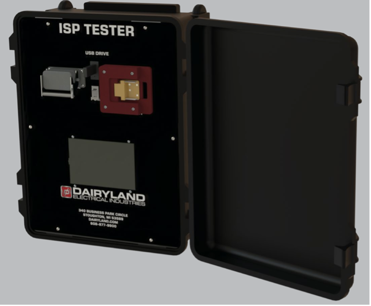
Figure 5: ISP Tester
The ISP Tester is an automated test device for performing in-circuit analysis of an ISP. The ISP is typically connected between the casing of a power utility pipe-type transmission cable system and the substation grounding system. Performing the functions of DC isolation and AC grounding for the transmission casing/sheath, an ISP is not easily removed from the system for the purpose of testing, therefore the ISP Tester performs an important role in analyzing an in-service ISP to determine its health.
The ISP Tester automatically evaluates the ISPs as-found condition and applies simulated AC fault signals to verify proper operation. It confirms that the ISP transitions into the low-impedance (ON) state under fault conditions, then reliably returns to its normal mode, blocking DC (from stray sources or cathodic protection systems) while allowing induced or coupled AC to pass to ground.
The ISP tester is initially configured via a simple touch panel interface. Following configuration, an automated test sequence is initiated by the operator. During the automated portion of the testing, the ISP is subjected to a multi-step test sequence controlled entirely by an on-board microprocessor. The sequence consists of various observational phases followed by two injections of a high current, short duration pulse which creates a temporary “fault” condition. During the test, the ISP is observed to verify that it properly triggers at either the 12.5V or 20V settings as initially selected on the touch panel and that the ISP properly recovers from a triggered condition. The brief high energy pulse causes the ISP to trigger only for a matter of several milliseconds, and a shorting system is applied to the external terminals to limit any influence on the external system. Operators of the ISP Tester should avoid contact with the exposed terminals of the ISP under test. Once initiated, the full test sequence requires approximately three to five minutes to complete. At the conclusion of the automated test sequence, informational data is combined with the actual test results and logged to a USB data drive.
If the ISP tester detects a problem during testing it will report the results in the home screen status box and abort any additional testing. There are fourteen possible failures and three successful results reported to the operator.
The ISP tester is available for purchase or rental. Please contact Dairyland for additional information.
Additional information may be found in the ISP’s technical literature, installation instructions and application guide. If you have any questions on the operation or testing of ISP’s, please contact Dairyland’s Technical Support team for guidance.
ISP Frequently Asked Questions
Frequently Asked Questions about Dairyland’s ISP
Dairyland’s ISP is the original solid-state AC conducting/DC blocking device designed for the corrosion prevention industry and features the most flexible and wide range of product ratings and applications available to the market. The ISP provides the widest range of features and ratings, including the highest levels of AC fault-handling capability – up to the highest typical transmission system faults making it the preferred product for power utility underground cable decoupling/bonding requirements. The following are some of the most frequently asked questions about ratings, logic board functionality, and installation.
To learn about the ISP’s different operating modes and how to test them, please see this article.
What is the leakage current of an ISP?
A relatively small DC leakage current is present during DC blocking, AC continuous operation. Figure 5 below provides an estimate of expected DC leakage current, which is dependent upon the DC voltage available at the terminals. We advise users to expect around 25mA per Volt.
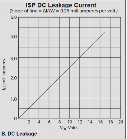
Figure 1: ISP DC Leakage Current
What is the importance of the logic circuit?
The most important component of the ISP is the logic-controlled circuit. This circuit determines exactly when the high current capacity thyristors should be turned “ON”. After a transient event, the circuit ensures the ISP returns to its normal operating mode, blocking DC while conducting AC. This prevents the thyristors from remaining in the ON state due to influence from a cathodic protection system or an external DC voltage source. The logic-controlled circuit, as with the entire ISP, is autonomous and does not require an auxiliary source of electrical power. It captures and stores the necessary power from any event that causes the voltage across, or the current through, the ISP terminals to reach the threshold level. Power is stored for a sufficient amount of time while the logic-controlled circuit deals with any foreseeable event.
The logic-controlled circuit includes a sub-circuit which provides a means for dissipating the stored inductive energy to prevent retriggering of the ISP. After this inductive energy is dissipated, the DC voltage will return to its normal steady-state value. The logic-controlled circuit then automatically goes dormant until the next triggering event occurs. The logic-controlled circuit differentiates between voltage rise caused by stored inductive energy, which should be safely dissipated, and external disturbances such as lightning surges or AC faults, where the ISP must trigger ON to protect itself and to limit voltage between its connected terminals.
Note on Revision 1 logic control circuit
The original logic-controlled circuit, designated as Revision 1, was introduced in the early 1990’s. This circuit revision does not protect an ISP from failure if the steady-state AC current is continually above rating. The Rev. 1 logic circuit does not include the following safety features:
- Prevention of capacitor overheating due to repeated retriggering if the ISP is operating above its steady-state ratings.
- Protection of the capacitor from excessive AC current that can occur below the absolute voltage threshold level of the ISP (applies when the 20V threshold level is selected).
- Provision for activating a flashing red warning indicator whenever the ISP is being repeatedly retriggered (due to application above steady-state rating).
ISPs with the original Rev. 1 logic control circuit were designed over 30 years ago, utilizing the most cutting-edge technology available at the time. Since that time, many technological advancements have been made. Dairyland now recommends that users of the older units consider upgrading to the newest Rev. 5 units.
Note on Revision 5 logic control circuit
Dairyland’s current ISP models utilize the latest Rev. 5 logic control circuit, which feature the following benefits:
- Inductive energy dissipation circuit that assures ISP remains OFF after fault event upgraded by 50% capacity for all models.
- Improved backup triggering of 26Vpeak if primary triggering fails.
- Prevention of capacitor overheating due to repeated retriggering if the ISP is operated above its steady-state ratings.
- Protection of the capacitor from excessive AC current that can occur below the absolute voltage threshold level of the ISP.
- 20V blocking voltage threshold standard.
- 90Arms steady-state AC current rating standard for models up to 68kA.
- 120Arms steady-state AC current rating for 118kA model.
What is the difference between 40 and 100 rating of logic control circuit?
These ratings indicate the maximum allowable DC current that can flow through the ISP during its conducting mode while still enabling the device to be automatically reset back to its normal mode after a fault condition. 40 is the standard rating, and it is capable of 40Adc. The 100 rating is optional, with capability of 100Adc.
Note that ISPs with Rev. 5 logic control circuit have 50% more capacity due to circuit improvements.
What is the impedance of an ISP?
For ISP units manufactured prior to 2020, the impedance value will vary depending on the steady-state current rating, as there were four options available. Impedance values are shown below:
| Steady-State ACrms Rating | mW (60Hz) | mW (50Hz) |
| 30A | 265 | 318 |
| 60A | 133 | 160 |
| 90A | 90 | 110 |
| 120A | 70 | 80 |
Table 1: Impedance values based on steady state current rating of an ISP
For ISP units manufactured in 2020 or later, only the 90A and 120A steady-state current ratings are available. The 90A and 120A impedance values shown above apply.
What is the difference in model numbers prior to 2020 and post-2020?
The ISP model number was streamlined in early 2020 for easier specification. Prior to 2020, there were numerous options that led to many variations of ISPs. The changes affected the steady-state current ratings, tamper-proof screws, and blocking voltage threshold.
The steady-state current ratings went from four options (30-120Arms) to only two options (90Arms or 120Arms), the blocking voltage threshold changed from two options (12.5V or 20V) to just the 20V option and finally, tamper-proof screws on the enclosure cover were made standard on all ISPs.
What is the purpose of the LED light?
The red LED indicator will flash approximately once per second if the DC voltage is above the voltage blocking level (12.5V or 20V), or if the steady state AC current is above the steady state rating of the ISP model (30A, 60A, 90A or 120A). Under normal operating conditions this LED should always be off.
If either of the above conditions occur, there will be an audible “clicking” sound as the thyristors are being switched.
Can ISPs be connected in parallel?
Single ISP models 35kA and 68kA should not be connected in parallel to double the AC fault current rating capability. The primary concern is that the logic control circuits are not synchronized to trigger at the same time during fault events. One of the units will trigger while the other one will not, thus the unit that triggers will see the full fault event and likely causing the ISP to fail.
For applications that require higher AC fault current capabilities, Dairyland recommends our highest rated ISP, the 118kA. This unit essentially has two single 68kA ISPs connected in parallel at the terminals and the logic controls circuits are synchronized together eliminating the issue mentioned above.
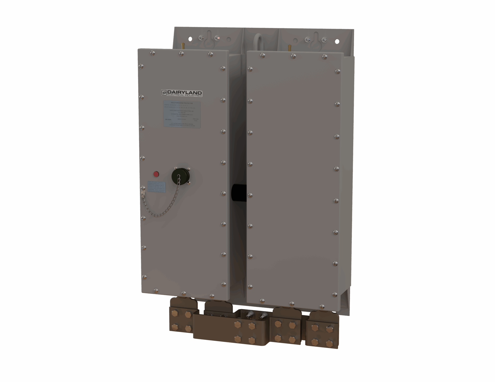
Dairyland’s ISP 118kA is recommended for applications that require higher AC fault current capabilities
Is an ISP listed for hazardous location use?
The ISP is a sealed, non-spark-producing device. This device meets the intent of ANSI/NFPA 70 (the U.S. National Electric Code) and CSA (Canadian Standards Association) requirements for Class I, Division 2 hazardous locations. The ISP has not been submitted for listing for hazardous locations because it is seldomly used in hazardous locations. If a listed device is required for hazardous locations, consider the PCR or PCRH, described in other literature sections.
Read more here about ISP’s different operating modes and how to test them.
If you have any questions regarding the information in this article, please feel free to contact us at techsupport@dairyland.com.
The Dairyland SSD was developed in 2005 as an alternative to the PCR. Both decouplers provide the same functions, but have a few key differences as well—most notably the ratings, package size, and cost. In the time since its release, the SSD has become one of our most popular decouplers, as it can be applied to a wide range of applications.
Dairyland technical experts and customer support personnel are often asked: What is the difference between “-R” and “non-R” SSDs? The following video graphically illustrates the primary differences, while also highlighting the specific applications for which they are best suited.
We are dedicated to understanding our customers’ needs and providing reliable products and service. If a solution to your problem does not yet exist, we’ll work to find one. Connect with us or call 608-877-9900.
This is the second article in our series designed to provide clarity amid the many new complexities surrounding the Mega Rule (read the first in the series). Corrosion control and repair criteria are central to Part 3 of the Mega Rule and here we focus on challenges around interference mitigation. Throughout this series, we also present solutions designed to help informed decision making and compliance.
The Mega Rule
To recap, the Mega Rule builds on and updates existing legislation designed to reinforce a risk management approach to the safety of natural gas transmission pipelines, natural gas distribution pipelines, and hazardous liquid transmission pipelines. Its third and final part became effective in February of 2023 with a compliance deadline of February 2024. It clarifies integrity management regulations from corrosion control requirements and repair criteria to post extreme weather inspection and applies to onshore gas pipeline infrastructure spanning HCA, and non-HCA.
The Mega Rule updates are challenging but Dairyland’s expertise and technologies are proven to mitigate interference, helping to deliver compliance, ensure safety and create competitive edge.

Background
For a range of logistical, land access and environmental purposes, it is a global norm for pipelines to share Right-of-Way (ROW) with high-voltage power lines creating a network of utility corridors. In these multi-purpose routes that often span long distances, AC corrosion risk is increased due to undesirable AC interference while also raising shock hazard risk to personnel who come in contact with the pipeline or appurtenances.
Challenge #2: Interference Mitigation
To understand the extent of corrosion and pipeline integrity, interference surveys are essential. Pipeline infrastructure and associated equipment have voltage limits and mitigative measures are required to reduce corrosion risk, lessen the risk to personnel, prevent costly damage and downtime.
To ensure compliance with the new regulations, interference surveys are undertaken when periodic monitoring indicates an increase in stray current, or new stray current sources are introduced. Sources of stray current can include co-located pipelines, structures, or high voltage alternating current (HVAC) or DC power lines (including from additional generation), a voltage up-rating, additional lines, new or enlarged power substations, new pipelines, or other structures. If the interference current is greater than or equal to 100 amps per meter squared a remedial action plan must be developed and implemented within a rule-stipulated time frame.
The risk of interference is heightened through the transferal of electrical energy onto a pipeline in multiple ways. Apart from the expected interference on multi-purpose routes, faults beyond the control of the pipeline operator, including lightning strikes, can take their toll on asset integrity. Furthermore, damage to overhead transmission systems from extreme weather or technical failures can increase the risk of line-to-ground damage. All these risks, and many more besides, must be mitigated against.
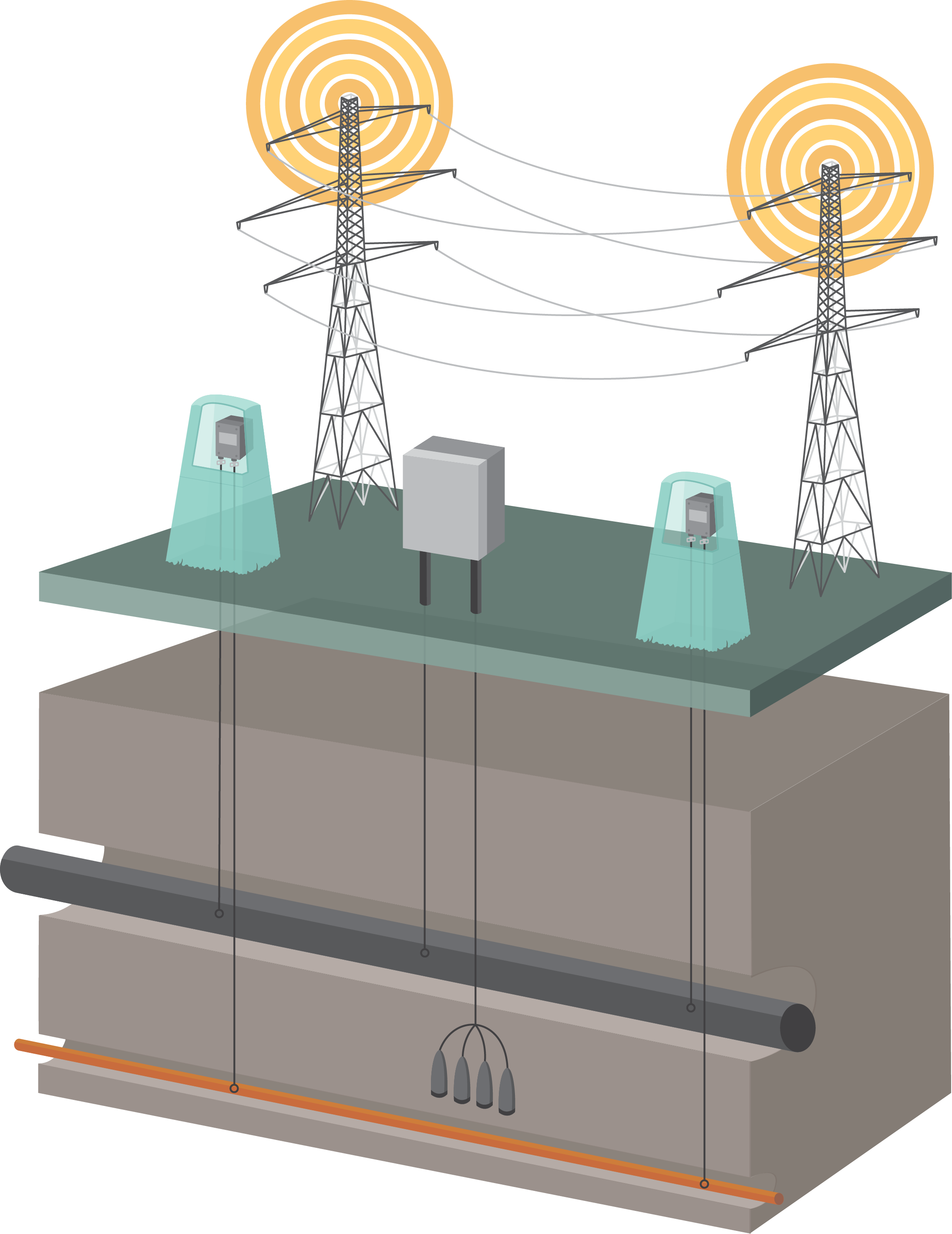
Solution #2: Interference Mitigation
Engineered interference mitigation systems can reduce AC voltages to an acceptable level, significantly reducing cost implications and improving safety over the operational lifespan of pipeline infrastructure. Dairyland products are proven, critical components of successful AC interference mitigation systems globally. Our decouplers such as the SSD, PCR, and PCRX, provide an effective grounding path that mitigates induced AC, while simultaneously maintaining DC isolation. Indeed, effectively utilizing decouplers in AC mitigation applications will help to minimize voltage differences to safe levels for both personnel and equipment when grounding is required to address safety and equipment concerns and isolation is required to maintain an effective cathodic protection (CP) system. Dairyland decouplers are appropriately rated to manage over-voltage conditions while simultaneously providing CP system isolation, protecting the integrity of your CP, maintaining a low impedance path to earth for AC and lightning, protecting your personnel and equipment.
With the Mega Rule impacting approximately 300,000 miles of existing onshore natural gas pipeline, and almost 20,000 miles of planned pipeline in the US, extending the life of these assets and building them in compliance with the regulations will require innovative technology and solutions.
Dairyland is here to help you make decisions on how our solutions can be applied to achieve Mega Rule compliance. We pride ourselves on being a reliable resource for complete technical guidance and our technical support staff is ready to support you in a variety of ways – even if you don’t end up needing our products.
Mega Rule Article 1: Accurate Close Interval Surveys
Mega Rule Article 3: RMV Installation Best Practices
At Dairyland we know that the scale and scope of the Mega Rule updates continues to present challenges to pipeline operators. This article is the first in a series by our team (read articles two and three), designed to provide clarity amid the many new complexities of the Mega Rule. We also present solutions to some of the key challenges to enable informed decision making and compliance.
Background
The Mega Rule builds on and updates existing legislation designed to reinforce a risk management approach to the safety of natural gas transmission pipelines, natural gas distribution pipelines, and hazardous liquid transmission pipelines. Its third and final part became effective in 2023 with a compliance deadline of February 2024.
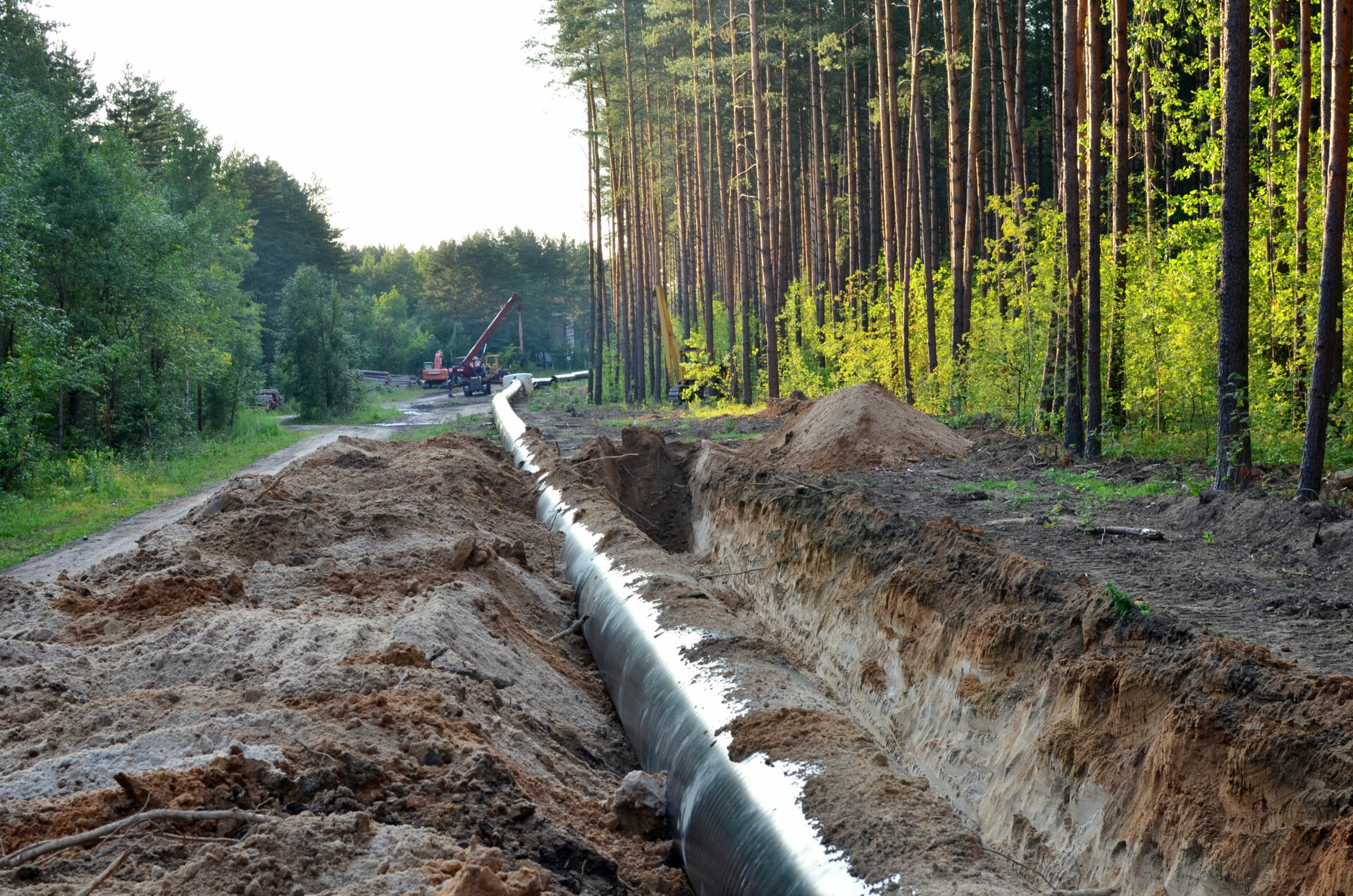
Natural gas pipeline under construction
Part 3 of the Mega Rule builds on its preceding parts that respectively tackle maximum allowable operating pressure (MAOP) and integrity management near high-consequence areas (HCAs), and the extension of federal safety requirements to onshore gas gathering pipelines with large diameters and high operating pressures.
It clarifies integrity management regulations from corrosion control requirements and repair criteria to post extreme weather inspection. It applies to onshore gas pipeline infrastructure spanning both HCA, and non-HCA.
Compliance with the Mega Rule in its entirety is firmly the responsibility of operating companies, the reality of which will vary depending upon the existing systems in place. Rule updates such as these can be challenging and implementing a compliant integrity management program has time and cost implications. However, Dairyland’s expertise and technologies can be put to work to ensure compliance, safety, and competitive edge.
Challenge #1: External Corrosion
To ensure compliance, pipelines must be monitored to determine cathodic protection (CP) Ievels. Definitively proving that a CP system is providing the degree of corrosion protection required is time-consuming and often inaccurate. Field testing has shown that interrupted surveys can sometimes be impacted by combinations of factors, such as pipeline coatings, soil resistivity, and the capacitance of traditional decouplers resulting in excessively electro-negative instant-off values. Nonetheless, where CP readings are below the required level, a close-interval-survey (CIS) is required to be completed. The CIS needs to be completed both upstream and downstream of the reading.
Any deficiencies must be remedied within a rule-stipulated window and following the completion of remedial action, an interrupted CIS must be undertaken again to ensure the pipeline potential readings are acceptable – incurring time and cost implications and increasing risk to personnel.
Solution #1: PCRX, The CIS Solution
The PCRX is the most sophisticated decoupler available globally. A solid-state, maintenance-free device, it is designed to simultaneously provide DC decoupling and AC continuity/grounding when used with CP structures. The PCRX provides typical decoupler functions with the additional benefit of electronically compensating for capacitance effects during interrupted surveys, including CIS. This prevents the device from contributing to errors in potential readings. The PCRX compensates to overcome capacitive effects, ensuring accurate and timely potential measurements. It does this without sacrificing the rugged over-voltage protection, AC mitigation, CP isolation, and safety grounding of Dairyland’s standard decoupling products.

With the Mega Rule impacting approximately 300,000 miles of existing onshore natural gas pipeline, and almost 20,000 miles of planned pipeline in the US, extending the life of these assets and building them in compliance with the regulations will require innovative technology and solutions.
In multi-purpose corridors where pipelines share the Right-of-Way (ROW) with high-voltage power lines, for example, corrosion risk is increased, as is safety risk to personnel. PCRX, however, will provide an effective grounding path that mitigates induced AC, while simultaneously maintaining DC isolation. This is possible because PCRX provides a low impedance to AC and high resistance to DC simultaneously. As a result, CP systems will continue to work efficiently, and pipelines plus personnel will be safe from undesirable AC interference.
With applications for retrofitting and new-build infrastructure, PCRX is proving to be an essential part of the modern CP system on pipelines and other protected structures for accurate CP readings while improving system performance and delivering the required safety protections.
Dairyland is here to help you make decisions on how our solutions can be applied to achieve Mega Rule compliance. Our technical support staff is ready to support you in a variety of ways, and always offer free personal consultations to help customers decide how to apply Dairyland solutions to your system.
Mega Rule Article 2: Interference Mitigation
Mega Rule Article 3: RMV Installation Best Practices
Dairyland decouplers play a crucial role in protecting personnel and infrastructure in various applications, including AC mitigation systems. It is important for users to understand how a decoupler will interact with external currents used during certain maintenance processes, like line locating or current surveys, to avoid inaccurate readings or more severe complications.
Line locating is a key operation for the pipeline industry, used to locate buried pipelines before performing routine maintenance or construction activities nearby. To locate buried pipelines, a transmitter is connected to the pipeline and sends various frequencies through it. A receiver, commonly referred to as the locator, is then used to read the signal from these frequencies above ground. If the locator is directly above the pipeline, the signal shows it’s exact depth and location. When performing pipeline locating, accuracy is imperative to ensure safe digging and/or accurate reads when performing other testing on the pipeline such as ACVG, DCVG, CIS, etc.
When locating, anything that is in proximity—such as a water line—could cause the signal to jump off the pipeline and follow that neighboring structure. Because the signal travels through soil to reach the neighboring structure, some impedance occurs, resulting in a weaker signal. If the signal becomes weaker, the locator is no longer following the intended pipeline.
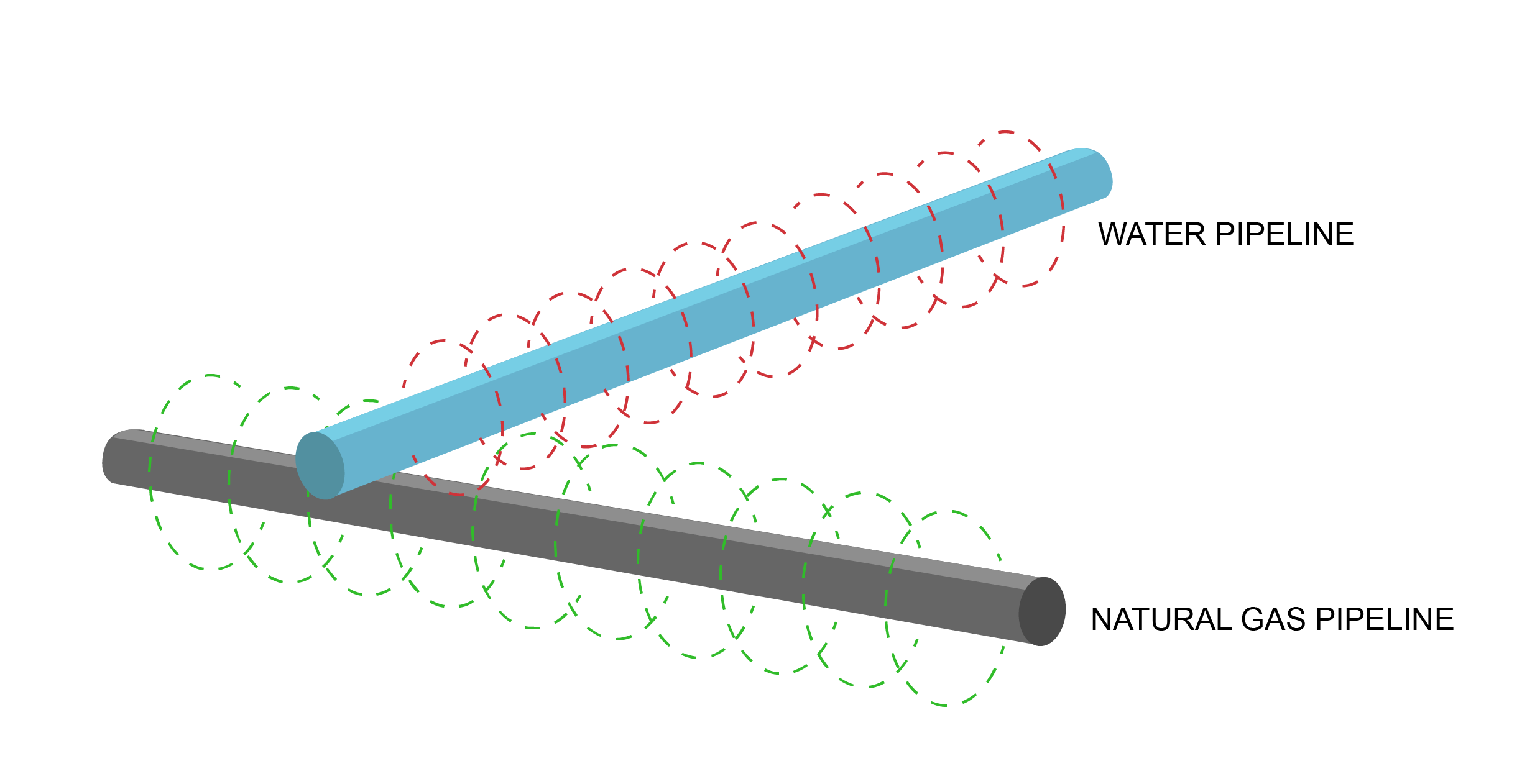
Figure 1. Locator signal travels along a natural gas pipeline and is picked up by a water pipeline
The signal can jump to anything that is physically connected to the pipeline—such as the grounding conductor of a motor operated valve (MOV) or an AC mitigation system. This again can cause the line locater veer off of the intended path. In this instance the signal will not necessarily be weaker, adding difficulty in determining if the pipeline is being followed correctly.
If a locator is following the signal being read from the grounding conductor of an MOV, the locator will discover this once they arrive at the electrical connection. It is more difficult to know if the locator is following the signal being read from the AC mitigation system.

Figure 2. Locator signal passing through a decoupler onto the AC mitigation wire
AC mitigation systems will most likely run in parallel with the pipeline that is being located. These systems are designed to mitigate the steady-state current from transmission towers that typically operate at 60Hz in the United States, or 50Hz outside of the US. Because Dairyland decouplers are designed to have a low impedance, any frequency above 7Hz will pass through the decoupler onto the AC mitigation system. If the locator jumps off the pipeline and begins following the path of the AC mitigation system, it won’t be immediately obvious, as the signal will not appear weaker like it would in the case of it following a foreign water line. This can cause location markings to be off by several feet.
For activities, such as line locating that involve the use a signal varying in frequency, as well as current surveys, ACVG, and DCVG coating surveys-Dairyland recommends installing a disconnect switch to prevent this current from moving onto to the connected AC mitigation system. The use of a disconnect switch is a quick and safe solution in these circumstances. View all Dairyland switches on our product accessories page.
For decouplers that are in an electrical circuit for electrical equipment grounding isolation, we do not recommend the use of a disconnect switch since these circuits should not be open for electrical safety.
If you should have any questions regarding the information in this article, please feel free to contact us at techsupport@dairyland.com.
Introduction
Dairyland’s Overwatch HEFPD is a new class of device, designed using our decades of experience in high-energy applications. With a design featuring Dairyland’s proven solid-state technology, Overwatch can withstand the powerful, long-duration events caused by AC faults, keeping sensitive track-connected equipment protected. Overwatch is rated up to 4000 amps for a 12 cycle (0.2 second) duration AC fault event as defined in AREMA 11.3.7, while also meeting the applicable requirements of primary surge protection as defined in AREMA 11.3.1.
This article provides information on how an Overwatch High-Energy Fault Protection Device (HEFPD) can be shown in relation to the wiring schematics of the railroad line diagrams. Overwatch has multiple options for the rail wire to terminate between the HEFPD terminals A, B, C or D with a fuse either in or out of circuit. Please refer to the Overwatch HEFPD Application Guide for more information on how these termination options can affect the fault ratings and overall protection of the bungalow equipment.
Please note, this article focuses on the rail-to-ground application only. For rail-to-rail equalizer or isolation joint wiring examples and ratings, please reference the Overwatch HEFPD Application Guide.
Rail-to-Ground Fault Protection Summary
When an Overwatch HEFPD is selected to protect signaling equipment in the bungalow, it is installed in the circuit between the rail and the bungalow using the track connected signaling wires. This application is known as rail-to-ground fault protection. Diagram 1 illustrates a track circuit one line diagram showing the track segments and train signals located at a road crossing, with a main track (T1) and a side track (T2).
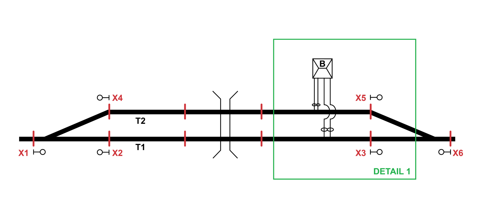
Diagram 1: Road Crossing with a Side Track
Existing Wiring
The track connected wires are typically a twisted pair of #6 wires that connect to each rail and terminate inside the bungalow onto an entrance board with surge protector devices (aka lightning arrestors) prior to their connection to signaling equipment. Detail 1 shows these existing track connected wires going into the bungalow (B) in the area of X3 and X5 on tracks T1 and T2. The wires for the main track (T1) are labeled T1S1 and T1N1. The side track (T2) utilizes wires T2S1 and T2N1
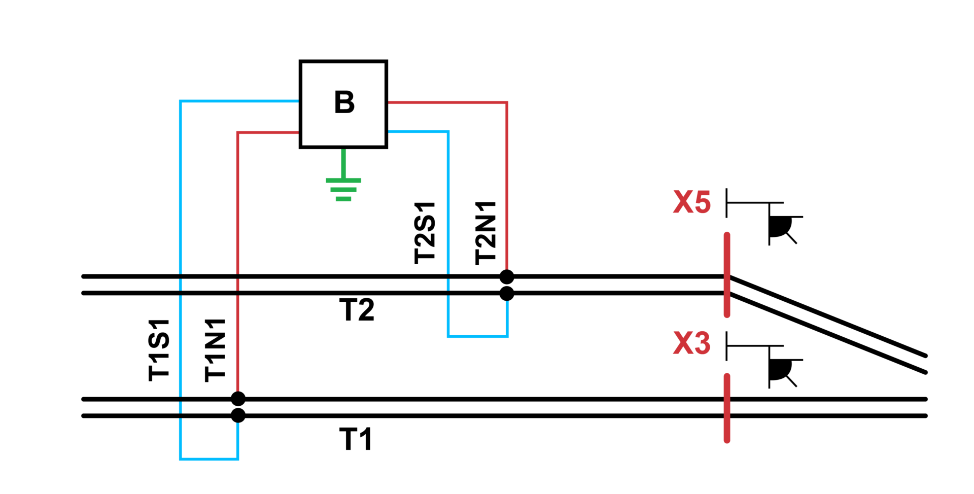
Detail 1: Existing Track Connected Wires
Overwatch HEFPD Installation Details
In this scenario, two Overwatch dual-channel devices will be connected to the track signaling wires as shown in Detail 2. Note that each dual-channel enclosure will protect two rails. In this case, Overwatch-1 is protecting the main track (T1) through wires T1S1 and T1N1. Overwatch-2 is protecting the side track (T2) through wires T2S1 and T2N1. Note that a grounding wire is connected from Overwatch-2 to the existing bungalow grounding ring.
Overwatch can be mounted either outside the bungalow, or if room allows, inside the bungalow. Its enclosure is weather rated for outside exposure (NEMA-4X) and constructed of a powder coated stainless steel. Overwatch is designed for Wayside Class B outdoor installation per AREMA part 11.5.1. The Overwatch HEFPD Installation Instructions have more information on mounting the enclosure.
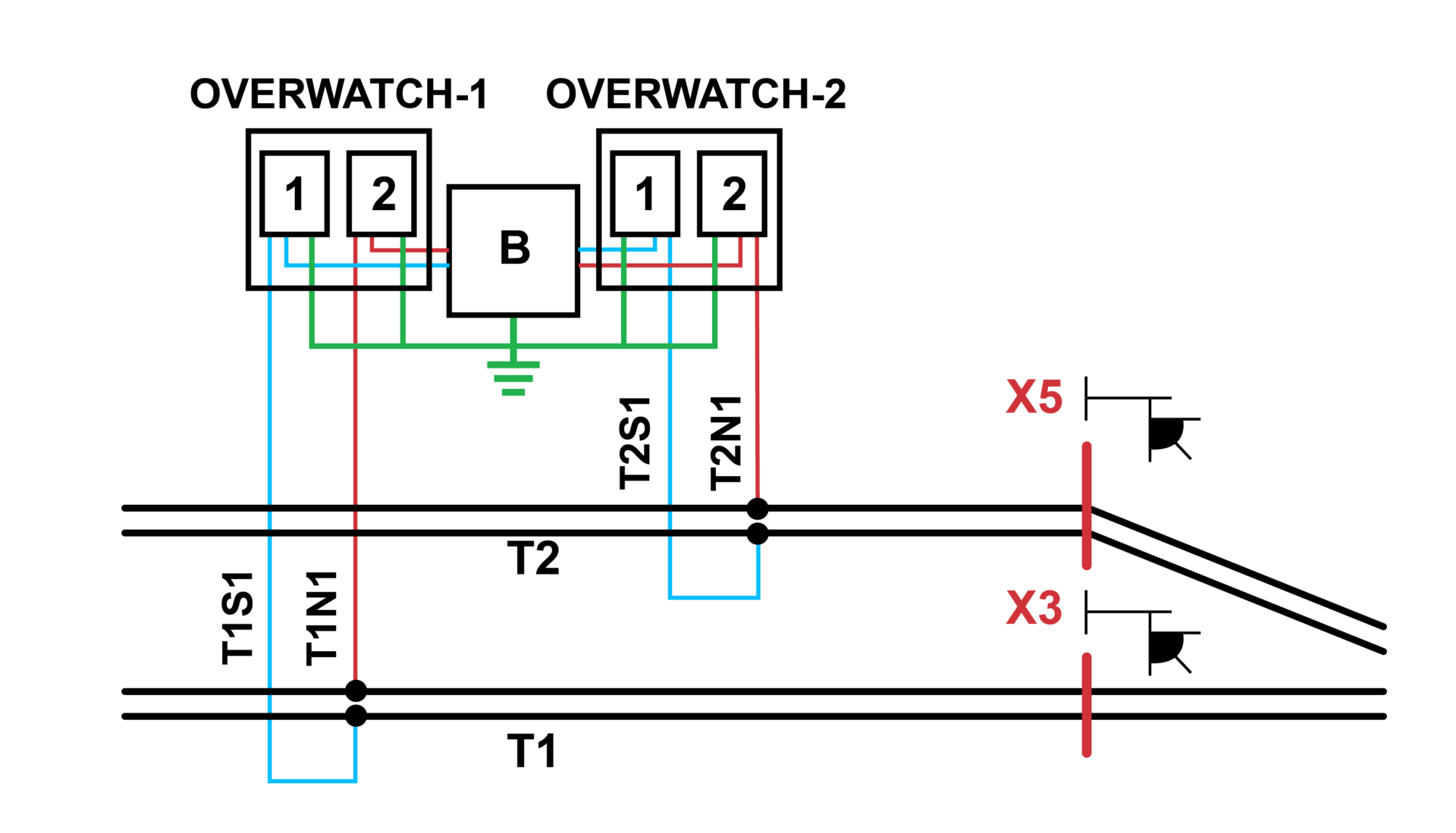
Detail 2: Overwatch HEFPD shown between Track and Bungalow
Overwatch HEFPD Terminations
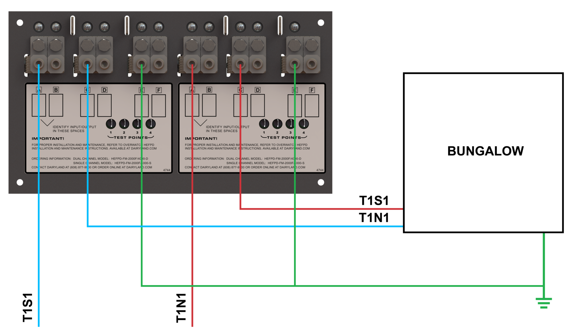
The track connected wires and the grounding wire will enter the Overwatch HEFPD enclosure through holes made by the installer at the bottom of the enclosure, utilizing rated conduit and conduit seals for the installed location. Detail 3 shows the wire connections made inside Overwatch-1 onto the provided terminals (or utilize a rated ring terminal on each wire end).
Note: this example uses the track wire connection option with the incoming rail wire terminated at A and the wire to the bungalow terminated at C, where the fuse is in the track circuit for a fault rating of 2000A. This is shown in Figure 1B of the Overwatch HEFPD Installation Instructions. See this document for more details regarding mounting Overwatch and other wiring connection options.
Detail 3: Track Wire and Grounding Wire Terminations inside Overwatch for T1
Rail Schematics with Overwatch HEFPD
Overwatch HEFPD can be shown as a fused surge and fault module in the schematics of the track wiring diagrams. Overwatch is installed upstream of the bungalow terminal board that has the surge protection devices (or lightning arrestors). See Detail 4 for an example schematic for the referenced Terminal A to Terminal C connection of the rail-to-ground application shown in the details above.
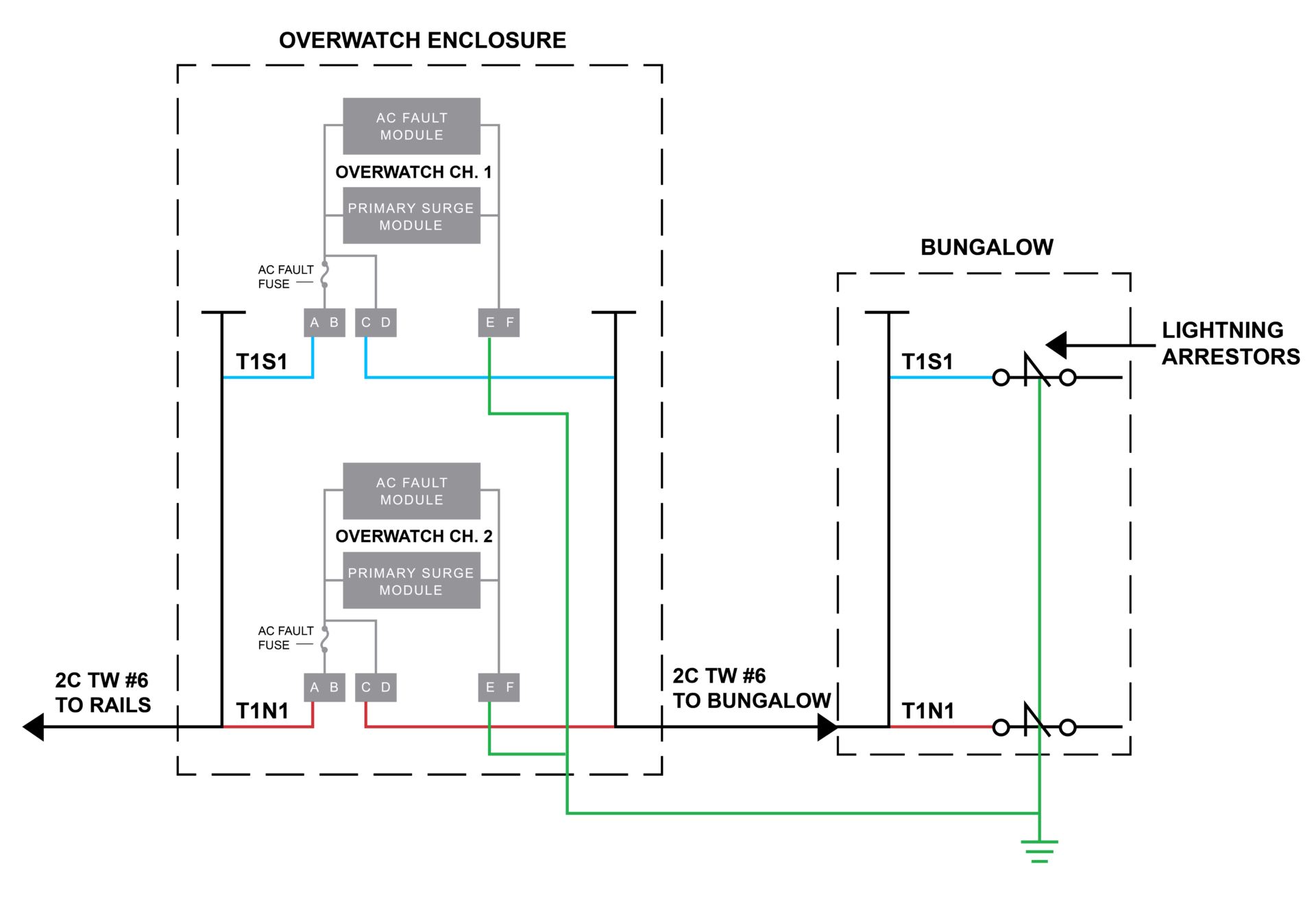
Detail 4: Bungalow Termination Schematic
Dairyland Support: We’re Here to Help
Additional installation details may be found in the Overwatch HEFPD Technical Literature and Installation Instructions. If you have any questions on the application of an Overwatch HEFPD on your track segment, please contact Dairyland Technical Support for guidance.
Though not common, sometimes, an application may require a rating higher than what is available as a single decoupler. For example, an AC mitigation project may call for decouplers rated for AC fault currents up to 20kArms. But the highest fault current rating in a single Dairyland decoupler is 15kArms. Similarly, a pipeline may have very high AC interference such that the continuous AC current through a single decoupler may exceed the standard steady-state rating of 45Arms. And occasionally, pipelines with higher CP potentials or those exposed to DC interference may require decouplers with higher threshold voltages to prevent them from going into conduction unnecessarily. Dairyland offers threshold voltages up to -6/+1V on some PCR models. But in some rare cases, even higher thresholds may be needed.
In such applications, multiple decouplers may be combined to create a wide range of effective ratings for AC fault current, steady-state AC current, and threshold voltage that otherwise may have been outside the application range of standard decouplers.
Increase Effective AC Steady-State and Fault Current Ratings by Connecting Multiple Decouplers in Parallel
The effective rating for both AC fault current and steady-state AC current increases in proportion with the number of decouplers connected in parallel. For example, the combination of two standard PCR-15kA devices, when connected in parallel in close proximity (i.e., connecting leads < 1m) as shown in Figure 1, has an effective AC fault current rating of 30kArms @ 30 cycles (50/60 Hz) and an effective steady-state AC current rating of 90 Arms. The threshold voltage of the combination remains unchanged from that of each individual device.
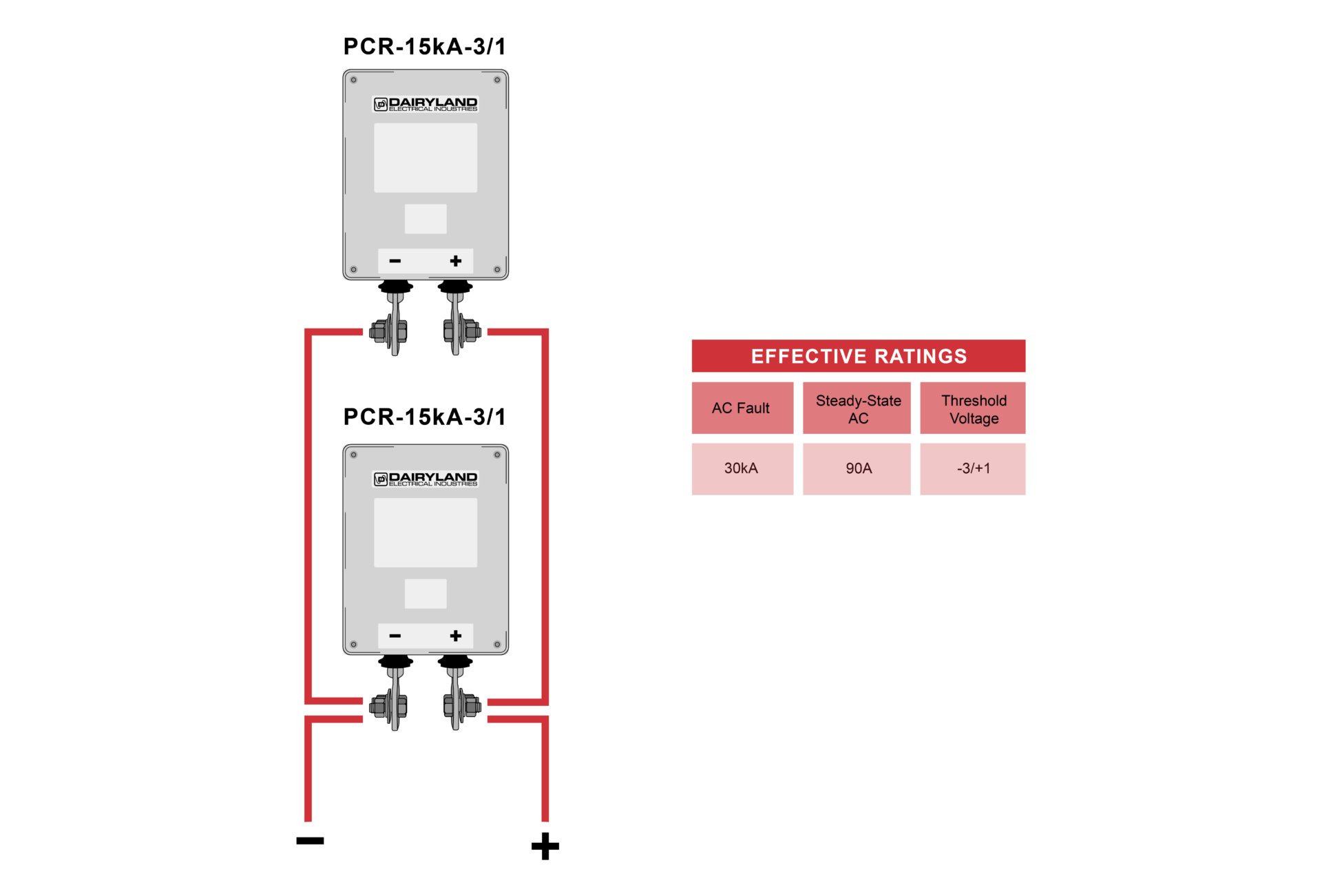
Figure 1. Increasing Effective Current Ratings by Connecting Devices in Parallel
CAUTIONPCRX decouplers should never be combined in parallel
|
When installed in this way, both the fault rating and the threshold voltage of each device must be equal to ensure that they each conduct in unison. Note that the total AC impedance of the parallel decoupler combination is reduced according to Equation 1. For example, the impedance of a single SSD or standard PCR at 60 Hz is 0.010 Ω. When two SSDs are combined in parallel, the equivalent impedance becomes 0.005 Ω at 60 Hz.

Increase Effective Threshold Voltage by Connecting Multiple Decouplers in Series
The effective threshold voltage of the series combination of decouplers is additive with the number of individual decouplers. For example, the combination of two PCRs, each with a threshold voltage of -3/+1V, when connected in series in close proximity (i.e., connecting leads < 1m) as shown in Figure 2, has an effective threshold voltage of -6/+2.
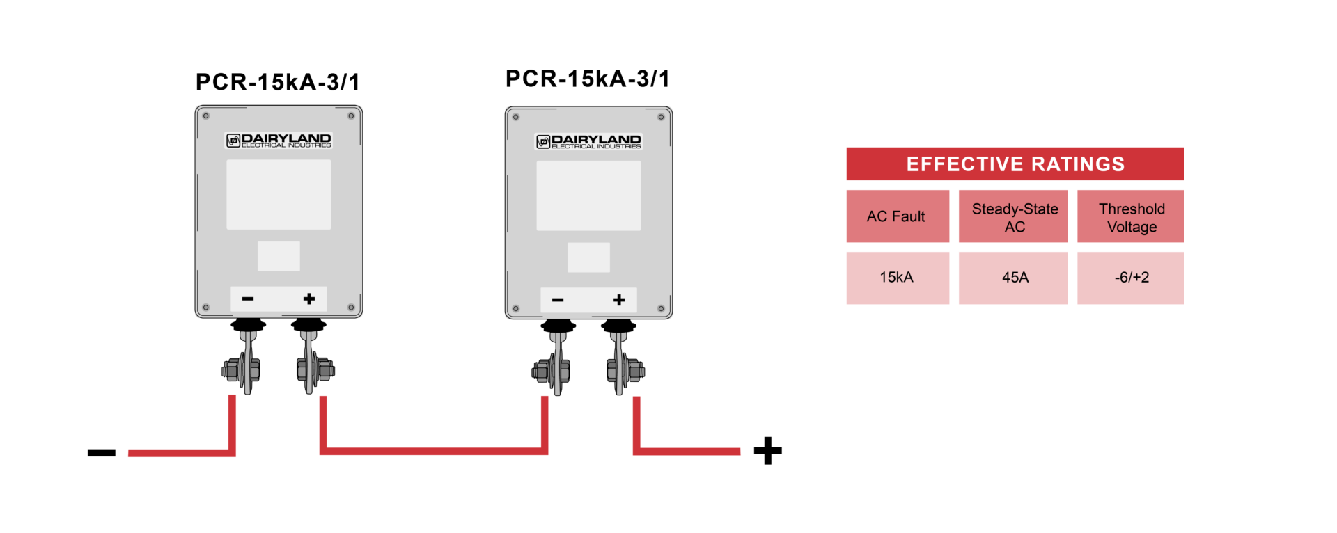
Figure 2. The effective threshold voltage of decouplers combined in series is the sum of the individual device threshold voltages
Note that the effective AC steady-state current rating and AC fault rating of the series combination will be equal to that of the lowest rated device in series.
Be aware that the total AC impedance is additive with the number of decouplers in series. For example, two SSDs or standard PCRs, each having AC impedance of 0.010 Ω at 60 Hz, will have a total impedance of 0.020 Ω at 60 Hz.
Other Ratings Created by Different Decoupler Arrangements
Though their use may be limited, note that several other interesting effective threshold voltages can be created by reversing the polarity on one of the decouplers and connecting them in either anti-series or anti-parallel as shown in the table below.

If you have any questions about combining multiple decouplers or Over-Voltage Protectors, contact Dairyland at techsupport@dairyland.com.
What is a DCVG Survey?
A direct current voltage gradient (DCVG) survey is a technique used to evaluate the effectiveness of corrosion protection systems on buried structures. This technique is used to analyze the coating condition and locate any coating “holidays” or coating defects on the buried pipeline.
In a DCVG survey, direct current (DC) is applied to the pipeline by using the pipeline’s impressed current rectifier or a portable power supply, and the voltage gradient is measured at intervals above the pipeline at the ground surface. The voltage gradient is measured by using two calibrated reference electrodes that are spaced a set distance apart. This measurement is the soil-to-soil potential difference and not the pipe-to-soil potential. Since most of the DC current will flow from the current source to a coating holiday, a voltage gradient will be present at a coating holiday and will appear as either current pick up or discharge.
Possible DCVG Survey Concerns with Standard Decouplers
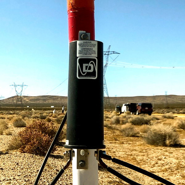
Dairyland SSD
During a DCVG survey, the impressed current rectifier or portable DC power supply is interrupted at a certain On/Off cycle similar to a Close Interval Survey (CIS). During the On cycle, the voltage gradient measured will be highest at the coating holiday. Conversely, during the Off cycle, the voltage gradient measured should not be present at that coating holiday as there is no DC current flow from the rectifier.
However, when standard decouplers (SSD, PCR, or PCRH) are installed nearby, this can affect the DCVG survey measurements and/or trigger a false reading with regards to coating holidays. This is due to the detection of a voltage gradient near standard decouplers and their connection to the grounding system. This may lead technicians to interpret this potential measurement as a large coating holiday and/or cause the operator to sway from the pipeline and follow the grounding system as it will be detected.
This voltage gradient is caused by the inherent capacitance of standard decouplers. These decouplers have a capacitor that is used to mitigate steady-state AC current from nearby HVAC lines. The capacitor holds a certain DC charge that looks like an uninterrupted DC source during the Off cycle of the survey. During the Off cycle, as the capacitor is discharged, it may still provide current to sustain the voltage gradient near the decoupler location and thus, may lead to an erroneous determination of a coating holiday.
The solution to this has been to temporarily disconnect the standard decouplers within the vicinity of the DCVG survey to remove this influence. However, this negatively affects the time to complete the survey and may increase the cost as well.
Solution For Faster DCVG Surveys
PCRX is Dairyland’s latest in solid-state decoupling technology. PCRX was introduced to the industry to virtually eliminate the capacitance issue found with standard decouplers. PCRX provides two main advantages over standard decouplers.
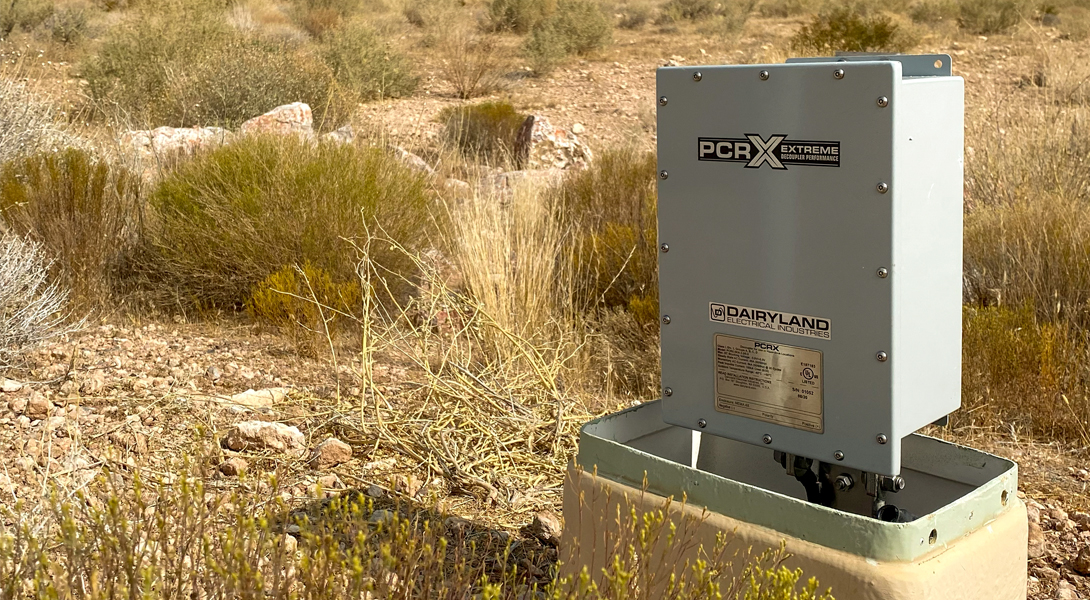
Firstly, it virtually eliminates the capacitive effects during the Off cycle, eliminating the voltage gradient and therefore, the possibility of an erroneous determination of a coating holiday. Secondly, there’s no need to disconnect the decoupler from the pipeline during the survey, always maintaining the connection to the mitigation system and keeping the pipeline grounded for over-voltage conditions. These benefits lead to safer and more efficient DCVG surveys.
We have a trained business development team ready to discuss your applications and product needs. Feel free to reach out to us to ask questions or consult on your needs – we are here to help!