
Customer Success Stories
Dairyland introduced its modular junction box—UltraBox—in 2019, and our customers have since applied them in numerous capacities for their unique projects. Now that people have had time to work with UltraBox, we wanted to follow up to find out how they are utilizing the boxes within their system, as well as the reasons why they chose the UltraBox over a more traditional junction box in the first place.
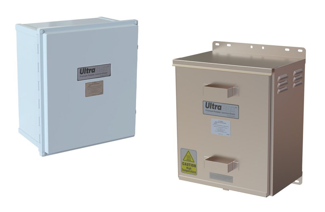
Polycarbonate and Stainless-Steel UltraBox enclosures
Ryan Simpson with Louisville Gas & Electric has purchased both the vented stainless-steel enclosure and the polycarbonate enclosure versions of the UltraBox, and this is what he had to say about how he is using them:
“We use the vented stainless-steel UltraBoxes for bonding connection, anode junction boxes, and multiple return structure connections. This enclosure is my favorite. It is so visually aesthetic that I really love incorporating them into our design. The din rails and modules are great for an organized enclosure. It is also extremely easy to change these components or add more. We have had several sites where we have had to increase the resistance and that was amazingly easy to do by just adding the larger resistor or placing several in series. This box gives so much room to work and install the components. It is our preferred vented box.”

“We also use UltraBoxes with polycarbonate enclosures for grounding connections, insulator bonding, and equipment housing. These boxes are genuinely nice and easy to customize. We prefer to add the components to the UltraBox in the field. The din rail provides an excellent way to mount and organize all the devices and it is extremely easy to add new components later without affecting the seal of the box. We just really prefer these UltraBoxes over other polycarbonate boxes.”
Tim Gubbins with Kinder Morgan has purchased and installed several polycarbonate UltraBox enclosures. He has used them as a rectifier bond box, an anode junction box, and a field junction box. He really likes the plug-and-play ability of the UltraBox, allowing him to configure them in the field and the ability to add whatever component is needed on the fly. When neighboring companies need to add a bond with Kinder Morgan, Tim has requested that they also use an UltraBox in order to keep things consistent.
“One of the benefits of the UltraBox is that it’s incredibly easy for technicians to build and configure them themselves in any location, but Tim also appreciates the option of having the UltraBox preconfigured by Dairyland so that it’s ready to install upon delivery.”
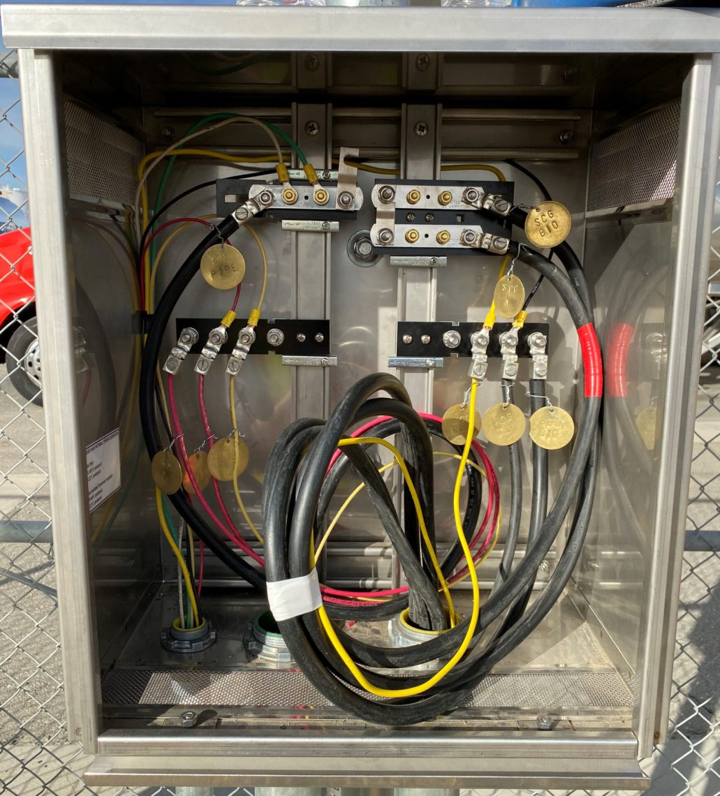
Matt Morales with Southern California Gas first became interested in UltraBox in 2018, when he saw an early iteration displayed at the NACE CORROSION Show for the first time. Since then, he has purchased many vented stainless-steel UltraBox enclosures and has overseen many customized installations. These customized installations allow Matt to add equipment that is not typically found in a standard junction box. He uses the din rail mounting system to attach his components to a blank G10 board, and limited only by his imagination, he can design truly customized boxes. One of the less-common items he is installing in his UltraBox is a reverse current switch that is required for DC interference as per one of the standards of Southern California Gas. The increased depth of the UltraBox provides him more room for these larger, less-common components.
In addition, Southern California Gas is now using UltraBoxes at solar installations to house solar power equipment.

UltraBox used in a Solar Application
From a maintenance perspective, Matt really likes the ability to replace a component after it has gone bad. Let’s face it, a shunt or a resistor is going to fail. To replace them in a traditional junction box, you will need to unscrew the back plate, often uncovering a mess back there. Generally, the wires are jumbled behind the micarta board and require untangling in order to find the one you’re looking for. However, with the UltraBox, you can make the installation nice and clean by having the wires run in a neat order. You also have easy access to all the components, allowing you to quickly replace one without worrying about loosening other wires or component in the process.
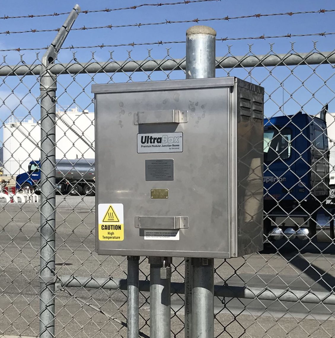
UltraBox secured with a padlock
Another key feature of the UltraBox, is the added flexibility to move components at any time. For Matt, this comes in handy when working with large gauge wire where, in some cases, it is easier to move the component to the wire as opposed to manhandling the wire to go to the component. The ability to move a component even a half-inch could make all the difference in the world and lessen frustration in the process. This equates to reduced labor and headaches from a long-term maintenance standpoint for Matt and his technicians.
Matt also appreciates the sturdy construction of the vented stainless-steel UltraBox and the added security it provides. It’s easy to secure the door using the clamping bar at the bottom of the enclosure, locking it in place with two bolts. For even more security, you can add a padlock to the eyelet at the bottom of the enclosure. Another benefit of the vented UltraBox enclosure is that the vents all have a small robust mesh that prevents animals, reptiles, and wasps from gaining access to the box.
Key UltraBox takeaways:
- Completely customizable design that can accommodate solar controls or RMUs.
- Improve efficiency by building the UltraBox in the field to the as-built conditions of the site.
- Compatible for multiple operators to customize to their own specifications.
- Added security from theft, vandalism, and small critters and insects.
- Maintenance-friendly design allows for easily replacement of individual components.
Summary
The title of this article was chosen purposefully to highlight the ways our customers “work with an UltraBox” as opposed to simply just installing an UltraBox. The ability to customize the UltraBox in the field allows the technician the flexibility to adjust the placement of components or modify the design and layout to meet their specific needs and preferences. These real-life examples not only show how people are using the UltraBox, but also illustrate the added ease and flexibility that it offers. If you’d like more information on how the UltraBox can work for you, reach out to our team for a consultation.
The most advanced decoupler in the world, the PCRX, is virtually invisible to interrupted survey testing and provides simultaneous DC decoupling and AC continuity/grounding when used with cathodically protected structures.
AC mitigation, where decouplers are installed between the pipeline and the mitigation grounding system, is the most common application for the PCRX. In most AC mitigation applications, there is significant AC interference with the pipeline resulting in several amps of induced current to flow through each decoupler to the grounding system. However, in some applications with relatively low AC interference, less than 1 Arms may flow through individual decouplers. In these rare cases, the PCRX may operate differently, and it is important to understand how this could affect your pipeline.
PCRX Operation with Low AC Current
The PCRX operates differently on pipelines having lower AC interference, specifically when the AC current flowing through the PCRX is below 0.6 Arms. The AC impedance of the PCRX varies with AC current, and below 0.6 Arms, the impedance is significantly higher than that at higher AC current levels, as shown in the chart below.
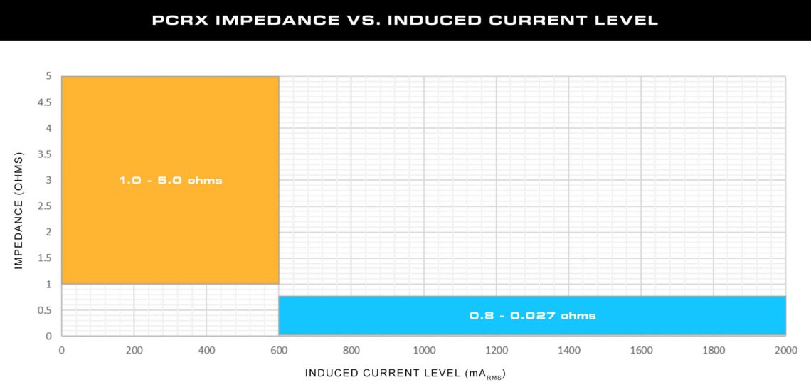
Figure 1
How Could This Affect My Pipeline?
In most cases, the higher impedance at low induced AC currents has little effect on the operation of the PCRX or the pipeline. Even at its highest impedance levels, the PCRX will maintain a maximum of 2 Vrms AC across the terminals under normal operating conditions, therefore keeping the pipeline AC potentials low near the PCRX pipeline connection. But other possible effects of the higher impedance at low current levels should be considered.
Influence on Blocking Threshold Selection
Since decouplers go into full conduction when the total voltage across the terminals reaches the threshold voltage, both DC and AC voltage across the terminals during normal operating conditions must be considered when choosing threshold voltage ratings. For example, assuming the maximum of 2 Vrms (2.8 Vpeak) AC across the PCRX terminals, the -4.5/+3.5 V threshold rating would permit a maximum DC operating voltage range of -1.7 V to +0.7 V. Similarly, in this case, the -5.5/+2.5 V rating would allow for a maximum DC operating range of -2.7 to -0.3 V. The PCRX threshold voltage ratings were designed to accommodate most DC operating conditions even under maximum steady state AC levels.
Possible Effect on AC Current Density
AC mitigation systems are designed to create a low resistance path to ground for induced AC. The impedance of any device in this path can affect the AC current density readings on the pipeline. This is why Dairyland decouplers, including the PCRX, are designed to have low nominal AC impedance. However, in rare cases when the PCRX impedance increases due to low induced AC levels, increased measured AC current density may be observed along the pipeline. The actual impact depends on the specific system design, soil resistivity and other system factors. The impedance values published in the PCRX Technical Literature should be incorporated into AC mitigation models when evaluating design goals for voltage and current density.
Potential Impact on AC Rail Interference Applications
It can take up to 15 seconds for the PCRX to transition from high to low impedance. For AC rail interference and other applications where there may be rapid transitions in AC interference from below 0.6 Arms to higher current levels, the PCRX may remain in a high impedance mode for several seconds even though the AC current has increased above 0.6 Arms. During this short transition period, the resulting elevated AC voltage across the terminals may cause the PCRX to go into conduction and a momentary loss in DC isolation. The PCRX would still provide AC mitigation and over-voltage protection. However, be aware that measured pipeline potentials may be affected during this brief transition period and should be discarded.
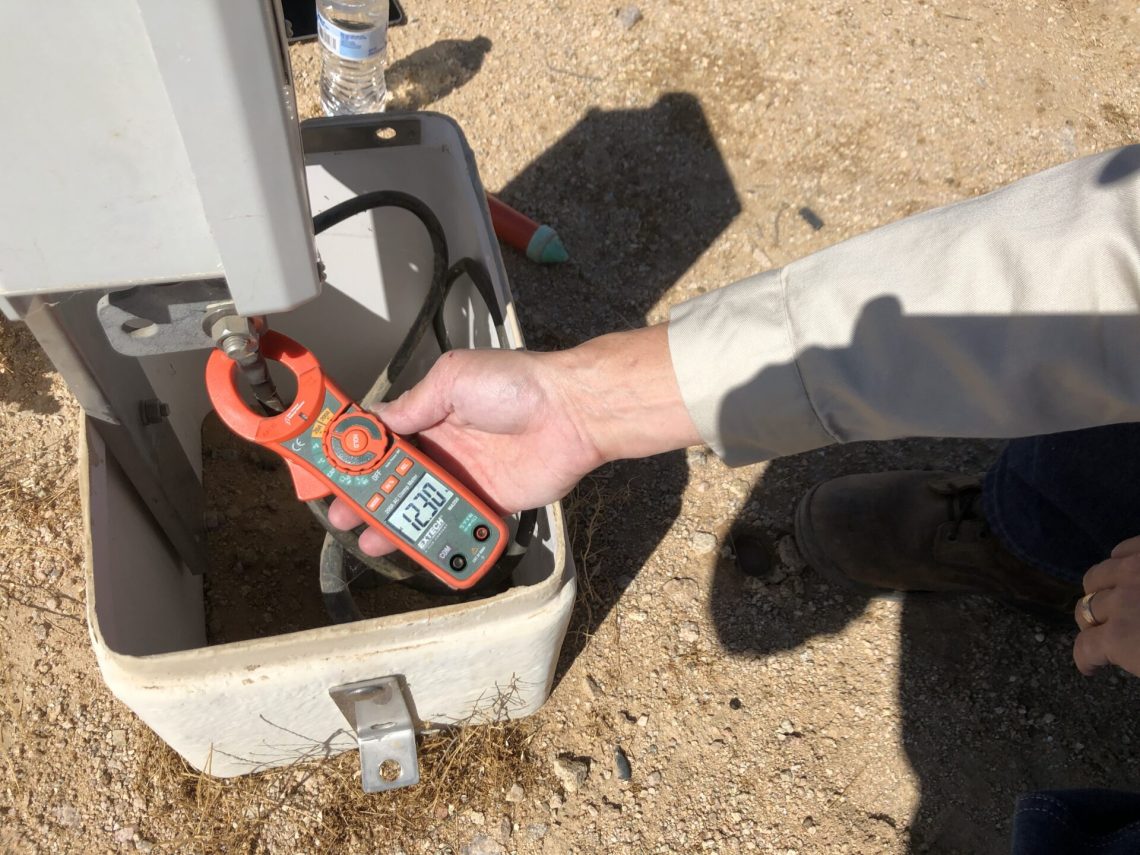
Figure 2
How can I know if my PCRX will have low AC current?
AC mitigation system modeling is recommended as a best practice for new installations. Modeling not only predicts an optimal design for control of AC interference, but also allows for estimating AC current flow through mitigation systems during steady-state and fault conditions. This information can be used to select proper decoupler models and determine at what impedance PCRX units will operate. PCRX impedance values found in the PCRX Technical Literature should be incorporated into AC mitigation models when evaluating systems with PCRX units.
For existing installations, the steady-state AC current can easily be measured using a clamp-on ammeter as shown in Figure 2.
Contact Dairyland for recommendations on PCRX application if steady-state AC current is either modeled or measured to be less than 0.6 Arms.
PCRX Will Always Improve Interrupted Survey Data
Even at low steady-state AC current levels, the PCRX will always improve the accuracy of instant-off measurements without having to disconnect the PCRX from the pipeline. And it will always provide DC isolation from grounding systems while simultaneously protecting the pipeline from over-voltage conditions such as AC faults and lightning.

Whether you are taking on a new construction project or performing maintenance on an existing pipeline, chances are you’ve come across the need for a junction box. But traditional junction boxes come with a variety of frustrations for users. With its modernized snap-in module system, Dairyland’s innovative UltraBox offers professionals a customizable and streamlined approach to address their individual needs.

What is a Junction Box?
A junction box is an enclosure that brings various wired connections to one central location and is a very common component found in cathodic protection systems. The junction box allows a technician to monitor cathodic protection levels—including voltage and current outputs—and to make minor adjustments, such as increasing or decreasing the resistance of a circuit. This is typically done to equalize the anode output on a ground bed so that the anodes are depleted equally over the life of the ground bed.
Typically, a traditional junction box is manufactured by mounting components (shunts, resistors, test points, etc.) on a fixed back plate inside of an enclosure. Although some companies have automated this process, most still build their junction boxes by hand. This requires each box to be custom built for each requested configuration.
Dairyland’s UltraBox – In a Class of its Own
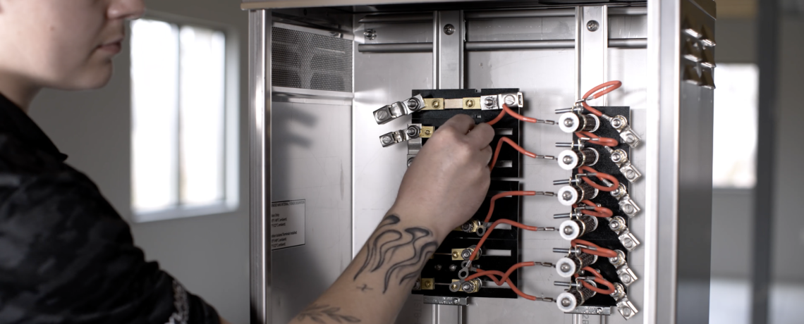
While there are many junction boxes out on the market, Dairyland’s UltraBox stands in a class of its own. What is the difference between a traditional junction box and Dairyland’s UltraBox? If you compare the exterior designs, they look pretty similar. While they may look similar from the outside, they aren’t remotely the same inside the cover. Opening the cover of an UltraBox you’ll find an entirely new mounting system designed to reduce frustration and increase customization. Taking a closer look at each component reveals a clip that is mounted on the underside of an insulating G-10 board. This clip easily attaches to a DIN rail in a matter of seconds and does not require any tooling to accomplish. Once everything is in place and attached to the DIN rails, the circuits can then be connected using the link bars for the shunts or corresponding wires for the resistors all with a 7/16” nut driver. Even the most complex configurations can be assembled in a matter of minutes.
Want to take a closer look? Check out these assembly videos to see how easy it can be to assemble custom configurations using UltraBox.
Examining the Benefits of The UltraBox
Is there anything wrong with a traditional junction box? Not really. They generally perform as intended, allowing technicians to monitor CP levels and make necessary adjustments. However, there was also nothing wrong with the rotary telephone, but there aren’t many people eager to trade in their smartphones for one today! Junction boxes perform their necessary functions, but like advancements in all sorts of fields, the UltraBox offers notable benefits for its customers to enjoy.
The UltraBox’s superior design puts control in the technician’s hands. It also removes common frustrations associated with traditional junction boxes, including long lead times and design revisions requiring junction box alterations. It also reduces the mis-wiring of components and frequency of loose connections, etc.
Let’s examine some common scenarios where traditional junction boxes can add frustration and review how the UltraBox addresses them.
Revisions to the original cathodic protection system design based on field conditions that require additional components to be added, like a shunt, resistor, or test point:
Traditional Junction Box
- Order a new junction box to reflect the new circuit design.
- Remove the back plate and manually add the components, taking care not to mis-wire the circuits or loosen existing connections, and finding space to maintain a clean and consistent circuit.
UltraBox
- Snap in the additional module(s) to reflect the new circuit design.
Replacing or adding a ground bed means replacing the junction box:
Traditional Junction Box
- A new junction box needs to be ordered to accommodate the new ground bed design.
UltraBox
- Remove the old ground bed wiring, add the additional modules for the new circuit design, and connect. There is no need to change out the UltraBox enclosure, and the modules may be able to be re-used if they match the new configuration.
Adding a test point to an existing junction box:
Traditional Junction Box
- Remove the back plate and manually add the components, taking care not to mis-wire the circuits or loosen existing circuits, and finding space to maintain a clean and consistent circuit.
UltraBox
- Snap in the additional test point module(s).
Long lead times for orders with standard components:
Traditional Junction Box
- Long lead times are typically due to the layout and custom manufacturing process needed to build a traditional junction box, making it necessary to incorporate this timeline into your project plan. Typically, it is not feasible for your company to have junction boxes in stock due to each configuration being unique.
UltraBox
- Custom-designed boxes can be ordered and shipped rapidly thanks to the UltraBox’s modular design. Because of the ease of assembly, your company could opt to keep enclosures and modules in stock and ready to be assembled from start to finish in a matter of minutes, regardless of unique configurations.
Junction box arrives and is not configured correctly as per design:
Traditional Junction Box
- Return to manufacturer for a replacement causing delays.
- Remove the back plate and manually correct the circuit design, taking care not to mis-wire the circuits or loosen existing connections, and finding space to maintain a clean and consistent circuit.
UltraBox
- Snap in additional modules or rearrange existing modules to reflect the correct circuit design.
In all of the above scenarios, the UltraBox’s modular design saves users the frustration of long wait times, the hassle of disassembling/reassembling or having to replace a junction box due to changes on their system.
Conclusion
Why has it taken so long to improve the junction box? We have all heard the saying “If it isn’t broke, don’t fix it” and “that’s how we have always done it.” Thankfully, not everyone prescribes to those sayings. Innovations come along to save time and reduce frustrations. The Dairyland UltraBox gives industry professionals a reason to rethink their junction box solution — reducing frustrations, saving time, and simplifying the process of applying and using a junction box on their systems.
Want to read more about the UltraBox? Click here to learn more.
Have more questions about the UltraBox?
Our tech support team is always available and happy to answer any questions you may have regarding products or applications. if you have additional questions or would like our assistance determining how to configure an UltraBox, reach out to us here.
Always Rugged. Always Reliable. — This is Dairyland’s promise when it comes to product design. With almost 40 years of experience, we create a safer world through highly engineered products as well as by sharing our expertise. Throughout our decades of client interactions, we’ve noticed some common industry misconceptions relating to over-voltage protection. Below, we examine a few of the most common.
AC Corrosion vs. Personnel Safety
Our first misconception is that AC voltage mitigation for safety will address AC corrosion. Although an exceptional mitigation system could potentially do so, AC corrosion is the result of specific current densities. Let’s look at the following chart:
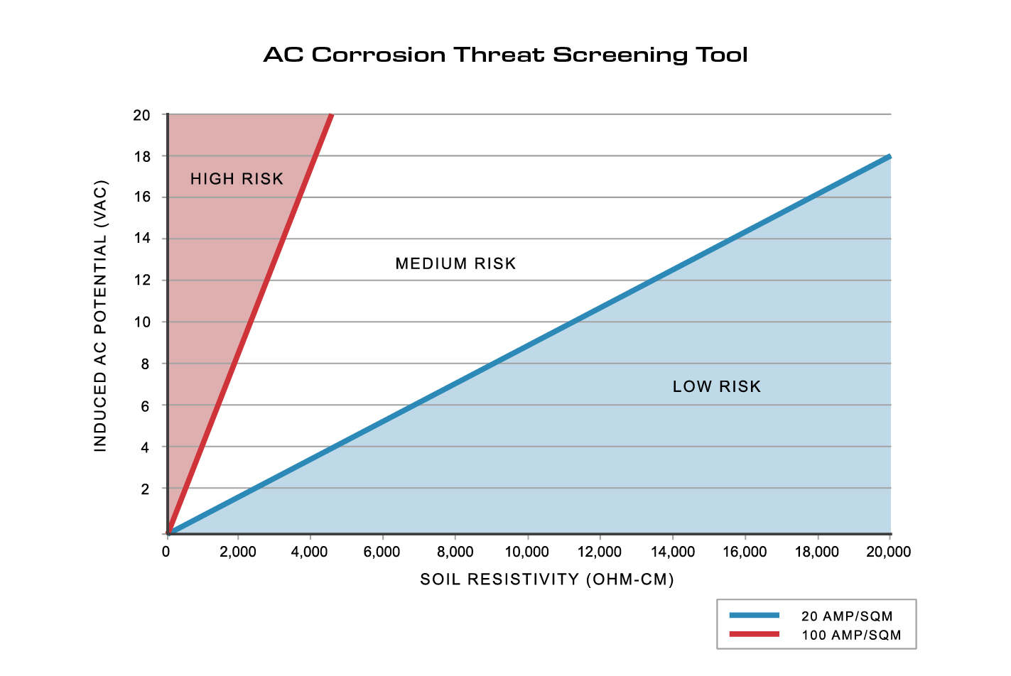
Figure 1: AC Corrosion Threat Screening Tool (Induced AC)
You can see that depending on your soil resistivity, even low levels of induced AC can create high-risk areas where AC corrosion can occur. It’s important to mitigate AC voltage with both personnel safety and AC corrosion in mind. If AC corrosion is a concern, work with your modeling design firm to make sure your mitigation plans account for both personnel safety and AC corrosion risk.
On that note, let’s talk about personnel safety and the industry standards addressing it. NACE SP0177, the corrosion industry’s guideline to managing voltage, suggests keeping your structure under 15 Volts-AC. The reasoning behind such a value relates to the average human body’s resistance of 1,000 Ohms and “let-go” current of 15mA.
Utilizing Ohm’s law, we get roughly 15 Volts-AC as our guideline. However, every human is different and much lower values could still be unsafe. All of us want a safe working environment, so we suggest you always work for the lowest AC voltage on your pipeline. And as proven above, the personnel safety standards don’t account for other phenomena.
Conductors: Inductance and Length
Our next misconception relates to conductors and the effects that current has flowing through them. I’m sure we’ve all heard of an “inductor” before – but do we understand the principle of this inductance effect?
Inductance is when an electrical conductor opposes the change in current flowing through it. This is very important to understand as we address situations like lightning. During these events, we see a spike of current which a conductor will resist. Like water pressure building in a hose, our conductor will create a large voltage drop across its length.
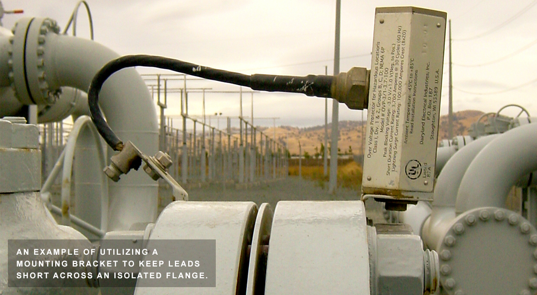
If you’ve ever used a Dairyland product to protect an isolated flange (like an OVP), you should now understand why we suggest keeping the leads short. What would happen if we used multiple feet of conductor to connect across the flange? Due to the inductance effect under lightning, that conductor will resist the flow of current, creating a voltage drop large enough to potentially damage the conductor coating and create arcing, which may result in the isolation flange not being protected. This would undermine the entire installation and cause damage to equipment. Click here for more information.
Conductors: Waveforms and Ampacity
Let’s address the next misconception while we’re still on the topic of wires: conductor length isn’t the problem in every application. As previously discussed, large electrical pulses like lightning (which behave differently than AC or DC waveforms) will bring about this inductance effect, creating concerns with conductor length. In AC fault scenarios, it’s not the conductor length that matters, but rather the ampacity rating of the wire itself. AC faults create a different waveform than lightning and are greater in duration, which means that the conductor must be able to handle the fault current for an extended period. Selecting the right conductor for each application is critical to ensure a safe, reliable installation. Click here to read more on this topic.
Total Electrical Isolation: The Truth
Now we’ll address our last misconception for this article. In the world of cathodic protection, we are forever plagued by the job of maintaining adequate protection levels. Mitigation systems, station grounds, electrical equipment grounds, and more, will always be a pathway to losing CP. It can be very tempting to want total isolation in these situations, however, that would be incredibly dangerous and could be outside electric code. Total isolation from ground on any structure or equipment would allow voltages to rise to very unsafe levels. That’s why we manufacture devices that simultaneously provide DC isolation and AC continuity: to ensure that CP levels are maintained, but each structure is safely referenced to one another.
This discussion is testament to the complexity of the Cathodic Protection industry. From understanding waveforms to personnel safety, there’s much to learn and remember. We hope this article has been beneficial to our readers and will continue to prompt best practices in the field.
For more information, please visit our website at www.Dairyland.com.
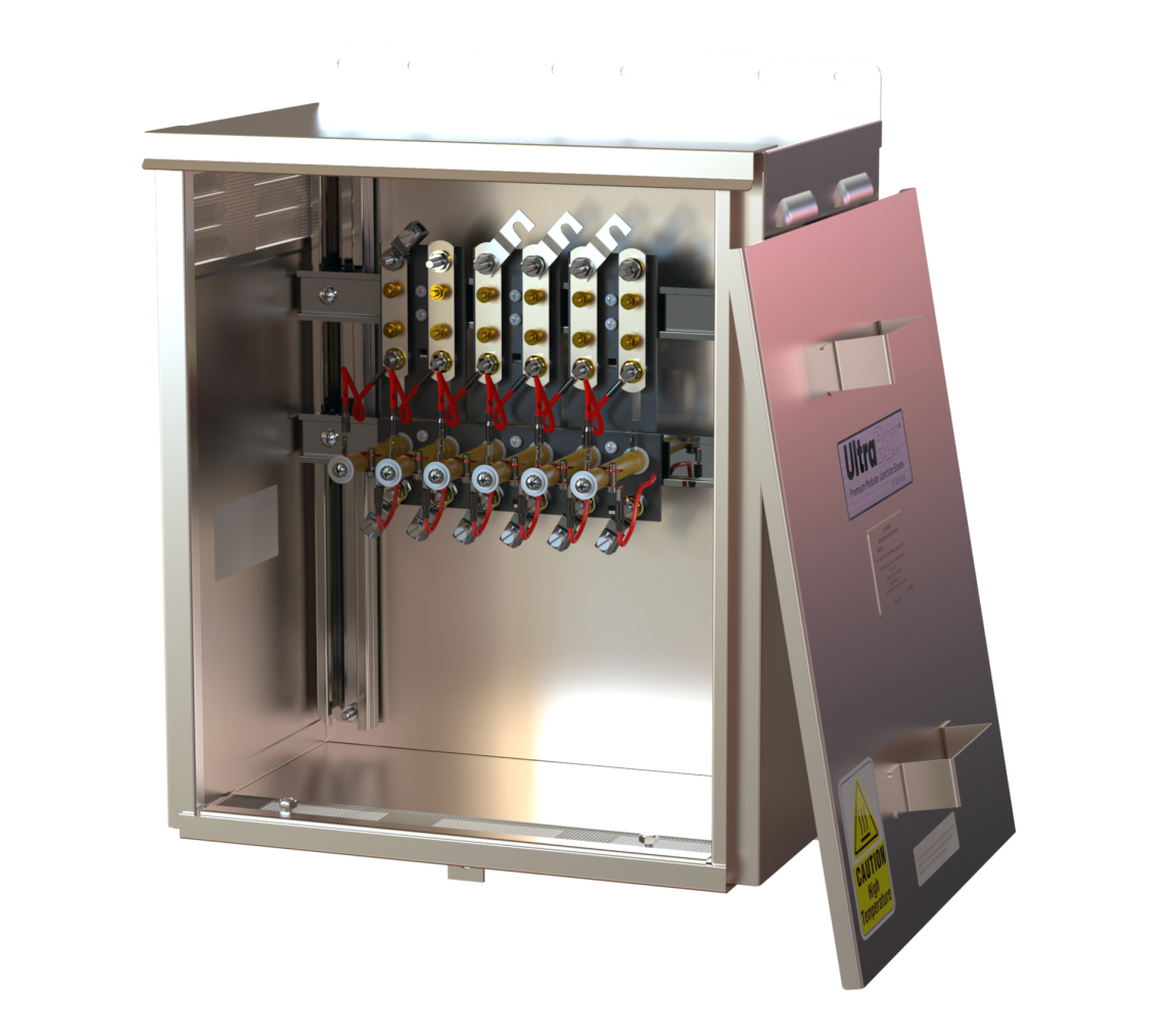
Dairyland’s UltraBox modular junction boxes feature snap-in DIN rail mounted modules with industry standard shunts and resistors to give you complete flexibility over the configuration and future expansion of your junction boxes.
The UltraBox can be used for virtually any junction box application related to cathodic protection. Whether needed for an anode junction box, interference bond, rectifier output box, positive/negative splitter, or an enhanced test station box, the UltraBox can be used anywhere and in any way that you use junction boxes.
Unlike traditional junction boxes with components fixed to a backplane, you can assemble and/or reconfigure the UltraBox in minutes – even on your truck’s tailgate – without any special tools. This can save you weeks waiting on custom-designed and fabricated junction boxes. And if you ever need to replace shunts or resistors or if your needs change over time, you can easily move or add components without having to disassemble the entire junction box.
Contact us for a live demonstration of how the UltraBox can be used with your CP installations. Below are a few examples of typical junction box applications and how the UltraBox can be configured to meet those needs.
Rectifier Junction Box Installation
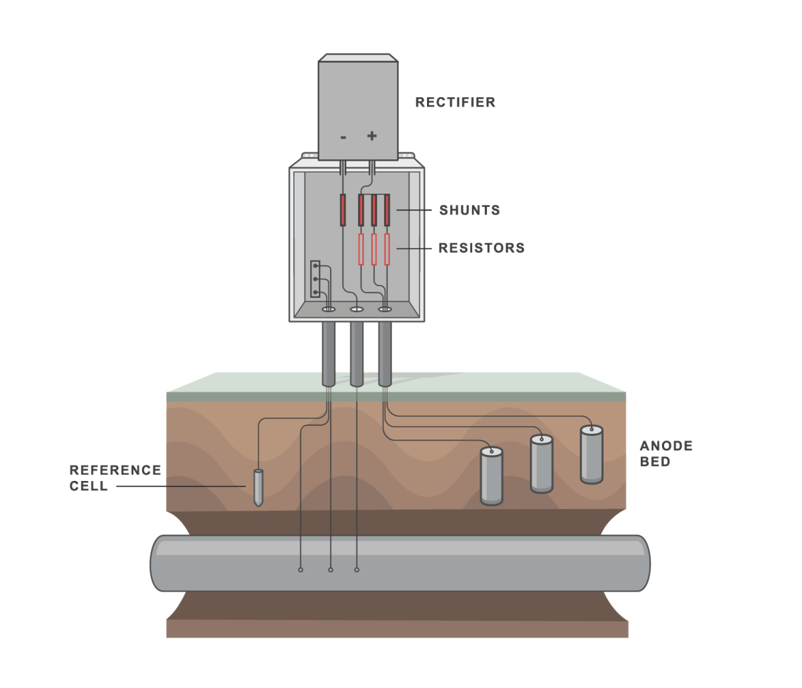
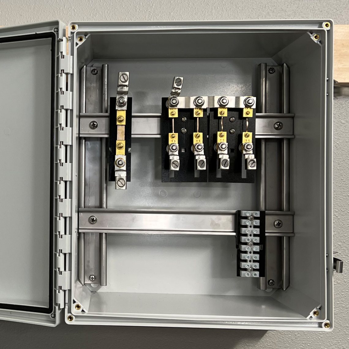
A junction box with shunts and resistors is often installed next to a rectifier with a shunt between the rectifier negative output and the pipeline and a parallel bank of shunts and resistors between the positive rectifier output and the anode bed as shown below. Sometimes, isolated terminals are needed to land test leads from a reference cell and/or the pipe. Note how the UltraBox can be quickly assembled for this application.
 |
 |
Average Build Time: 5 minutes
Anode Junction Box Installation
Used at the rectifier or closer to the anode bed or deep well, an anode junction box is connected between the positive rectifier output and a bank of anodes. An anode junction box often has both shunts and resistors but may have only shunts. With the UltraBox, it’s easy to add in resistors in the future if needed. Note how a header shunt, used here to measure the total current to the anode bed, is connected in the UltraBox.

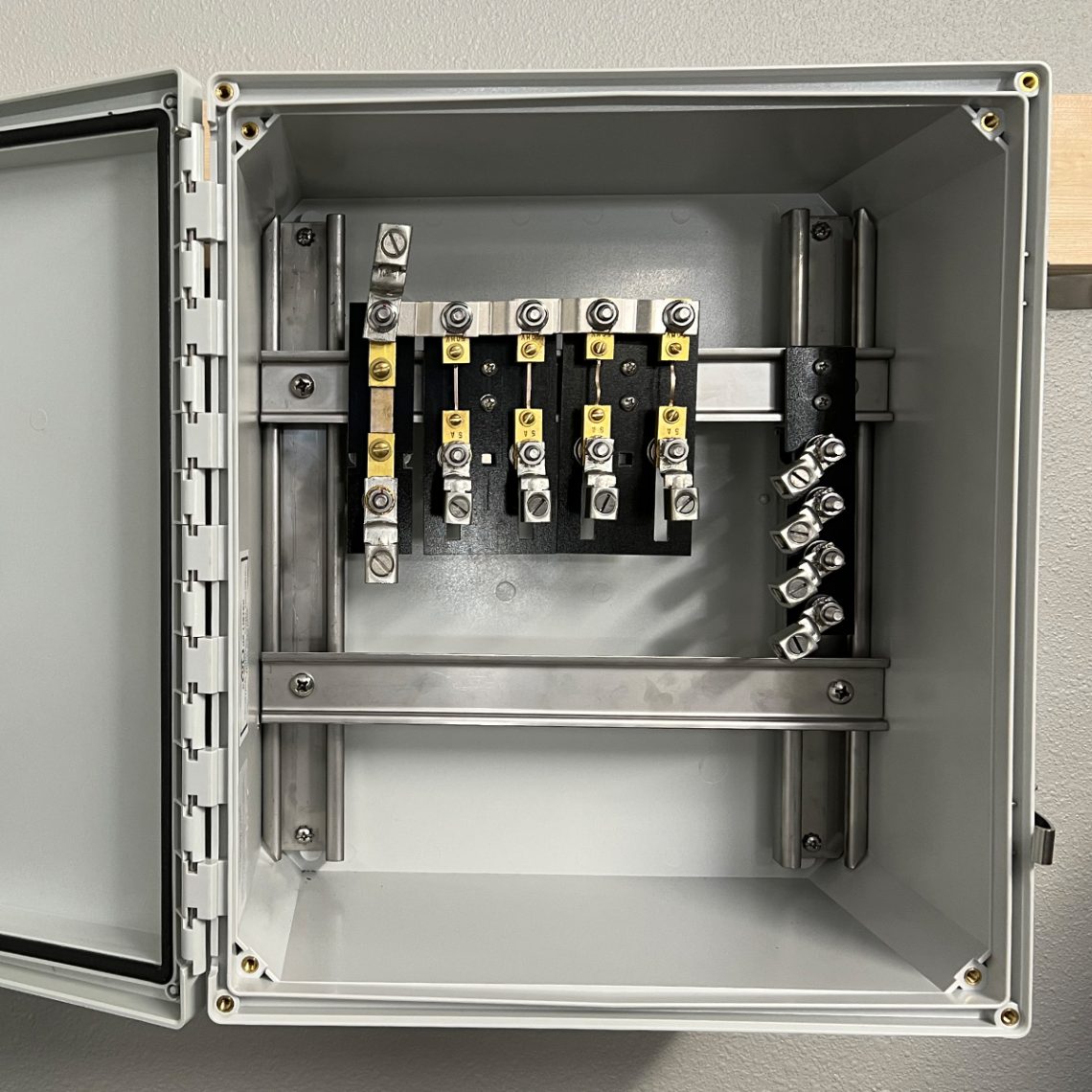
Average Build Time: 3 minutes
Field Junction Box Installation
Used to measure and/or control current to multiple pipelines, a field junction box is installed in the negative connection between the rectifier and the pipelines and is usually located remote from the rectifier or anodes. A similar configuration can also be used to manage interference between pipelines.
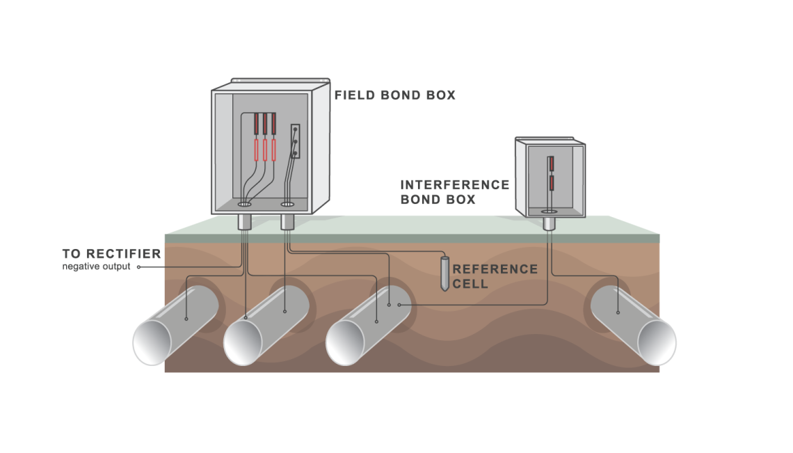
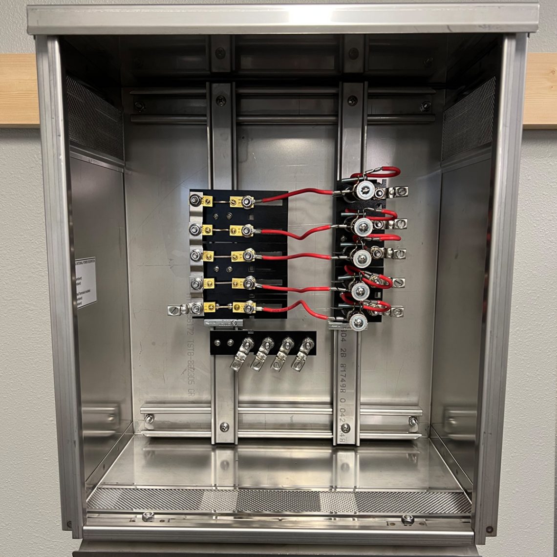
Field Bond Box |
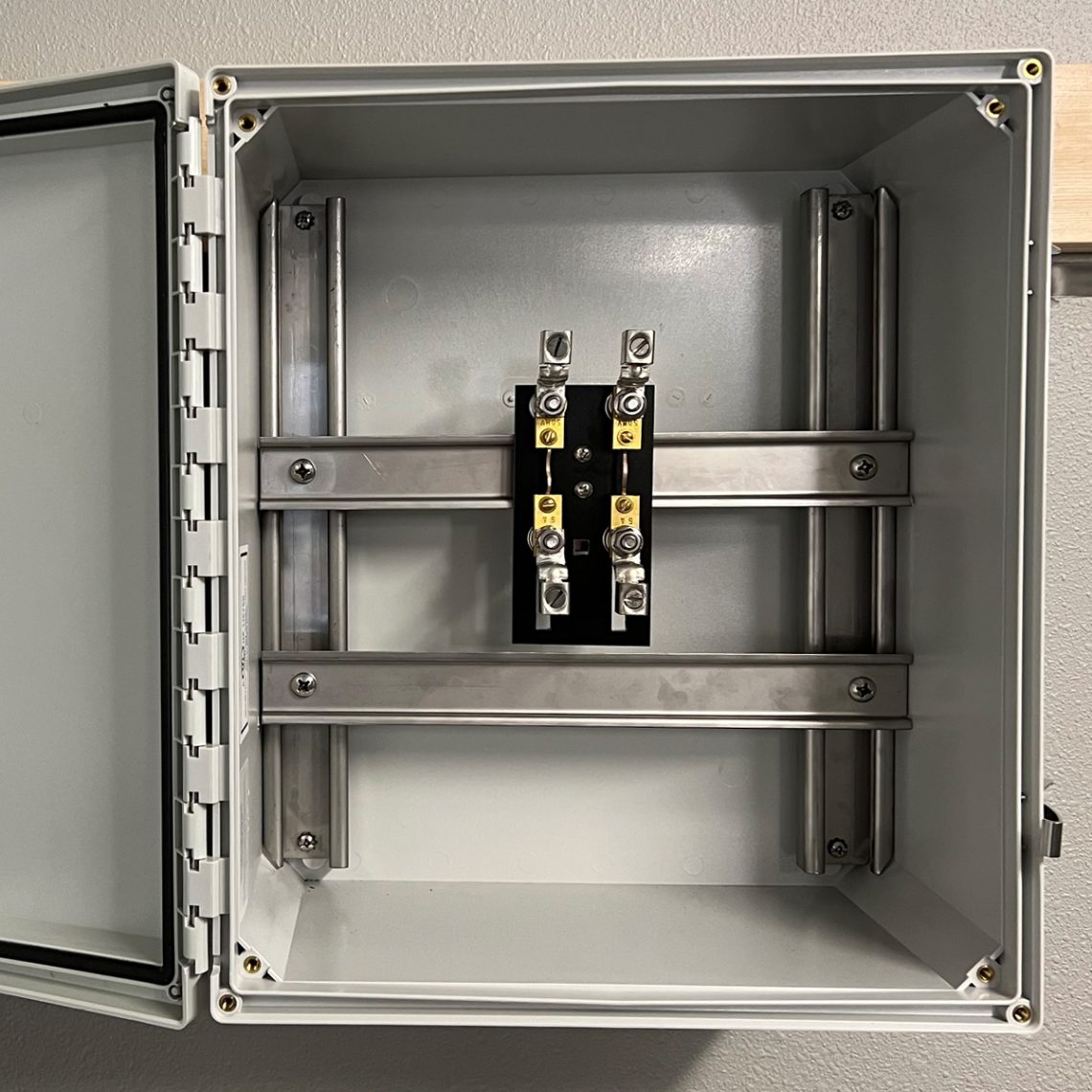
Interference Bond Box |
Average Build Time: 5 minutes
The following is an interview conducted by Dairyland Business Development Leader, Tim Bechtel, with Paul Sedlet, the President of Accurate Corrosion Control, Inc.
Paul has been working in the corrosion industry for over 35 years. He is a Cathodic Protection 4 Specialist (CP-4) and holds a degree in mechanical engineering from University of Arizona. Like others who have been in this industry for as many years, Paul has installed his fair share of junction boxes for a wide variety of purposes. With his history, we thought he would offer some good feedback and insight on the Dairyland UltraBox when comparing it to the traditional-style junction box.
Dairyland’s UltraBox is a customizable modular junction box that uses a moveable din rail mounting system to connect modules with industry-standard components, such as shunts and resistors. The UltraBox can be configured and assembled on the spot.
Unlike Dairyland’s UltraBox, a traditional junction box has these components on a fixed backplane. As a result, they must be pre-ordered from the manufacturer and configured in the factory, making modifications in the field quite challenging.
Thank you to Paul for taking the time to sit down with Tim to talk about one of Dairyland’s newest products: the UltraBox.
Tim: Any guess as to how many junction boxes you have installed over the years?
Paul: As a company, it’s in the many hundreds. Personally, I would say I’ve installed about 100.
Tim: What do you use junction boxes for mostly? (Anode junction box, interference bond, rectifier output box, positive/negative splitter, test station box).
Paul: We use them for all of the purposes you state. It varies by industry regarding what types and purposes the boxes are utilized for. They’re used, of course, wherever CP wires need to be terminated and monitored.
Tim: Historically, what is the most challenging aspect of installing a junction box?
Paul: I would say one of the most challenging aspects of installing a junction box is getting all the wires to fit and terminated to the locations you need them. Many CP cables are large—#2 HMWPE insulated or bigger—so they’re stiff and hard to bend. And sometimes the wires are too short (if it’s a replacement box), so they don’t reach where they’re needed.
Tim: Comparing a traditional junction box to an UltraBox, what type of planning do you need to do when it comes to ordering?
Paul: With a traditional J-box you need to know exactly how many wires you are terminating. These could be bond wires, test wires, reference cell, coupon, or anode wires. One big advantage of the UltraBox is that you can have a plan, but if something was missed, different than expected, or changes, it’s usually not a problem. That’s because the system is made to be adaptable/changeable — it’s plug and play. For example, if you need another shunt circuit, just add one to the rail. In a traditional J-box, if you need another shunt circuit, you would need to take everything apart, drill holes in the board, find the hardware, and reinstall it. This all takes a lot of time, and increases the chance of something being wired wrong as well.
Tim: Have you had issues in the past where the planned installation needs to be modified once in the field? What kinds of costs or delays are associated with that?
Paul: Oh sure, that happens all the time. Or we do an installation as planned, but shortly after something changes. It just happened this week, actually. Fortunately we’d installed an UltraBox, so now it’s an easy modification. In this case, the UltraBox was installed for a pipeline crossing with interference. It was designed for sacrificial anodes to drain the stray current, and it worked great. But conditions changed, and now an interference bond is required. The company [I was working with] specifies a reverse current switch for their interference bonds, so it’s an easy fix now to just add that to the rail. With a traditional box, it likely would have required replacing the entire box, or best case scenario spending half a day rebuilding the box to accommodate the additional component.
Tim: Most customers are concerned with costs. Because the UltraBox is a premium product, it costs more than a traditional junction box. Could you tell me why someone would choose to spend more money for the UltraBox over a traditional junction box?
Paul: It’s a bit more for the box up-front, but what’s really expensive is labor. The UltraBox saves you time on the installation, future maintenance, and especially if any modifications are ever needed.
Tim: Once installed, I’m sure most junction boxes rarely need to be modified. Could you tell me why someone might need to modify a junction box after it has been installed and has been in service for a while?
Paul: It’s surprising how many times J-boxes do need to be modified. For example, a new pipeline is installed in a common corridor. Or sacrificial anodes are added at a crossing. Things like that.

Tim: It sounds like there are some advantages to go with one over the other. Could you tell me what you think is the greatest advantage of the UltraBox over a traditional junction box?
Paul: Ease of installation and the ability to modify it, for sure. The extra room in the boxes is a huge advantage as well, as is the fact that the din rails can be moved up and down. It really makes installation faster. Another thing I really like about the UltraBox is that all the connections are visible. With traditional boxes, there’s often connections behind the board that you can’t see without taking it all apart. And traditional boxes require maintenance when the hardware becomes loose, which requires hours to take it all apart and tighten things. It’s surprising how often that’s necessary, but anyone who’s worked in these boxes has had to deal with it. That problem is solved with the UltraBox.
Tim: It sounds like the UltraBox is a great option to have in your toolbox to tackle any project you have, but especially handy to tackle the unknowns that occasionally pop up.
Paul: Exactly. It’s a huge improvement over traditional J-boxes. And I really like that we can have all the parts in stock to build whatever we need, on the tailgate and at a moments notice. It’s a better product and a real time and money saver!
Tim: Wow, thank you Paul for all of that great insight and information on your experience with junction boxes and Dairyland’s UltraBox. I truly appreciate the time you have given to talk with me today, and all of the great feedback you provided.
Paul: Thank you, Tim. I appreciate all Dairyland does for the industry and the great support you all provide!

The PCRX represents the next leap forward in solid-state decouplers. It features active capacitance compensation, which addresses issues related to slow interrupted response associated with the capacitance of traditional decouplers.
Customers have been looking for a solution to capacitive effects during interrupted survey testing for a long time. With the addition of the PCRX to Dairyland’s product line, customers have had a wide variety of questions about this new, innovative technology. Our technical support team took time to answer the most frequently asked questions.
Dairyland Tech Support: We are always available and happy to discuss these questions or help customers to decide what products are right for their applications. We hope people will reach out to us if they have additional questions.
Let’s jump in with the first question everyone asks: with this new active capacitance compensation technology, how does the PCRX overcome capacitive effects?
The PCRX utilizes a proprietary technology that has been developed over the last decade of design and testing. The PCRX uses this technology to recognize when an interruption cycle has been started on a CP system and it is able to very rapidly reduce the capacitive effects that are found on traditional decouplers.
Does the PCRX still perform normal decoupler functions for faults, steady state voltages and lightning?
Yes. Like our other decouplers, the PCRX is a solid-state, maintenance-free device, designed to simultaneously provide DC decoupling and AC continuity/grounding when used with cathodically protected structures. The PCRX continuously provides an effective ground path for steady state AC, AC faults and lightning, even during the off cycle of the interrupted circuit. It performs the same functions you are used to with the SSD or the PCR.
What about product ratings? Folks who have used the SSD and PCR for a long time are used to certain fault current ratings, blocking thresholds etc. Are the PCRX product ratings the same?
The ratings for the PCRX will be familiar to our customers, although there are some differences. The ratings for fault current and lightning should be relatively familiar to most PCR and SSD users. The PCRX is being offered with fault current ratings of 5ka, 10kA and 15kA for AC faults, and a lighting rating of 100kA crest (8 x 20 µs waveform) — these are similar ratings to our PCR product line.
The PCRX is available with two blocking voltage threshold ratings of -4.5V to +3.5V and-5.5V to +2.5V. Similar to the blocking voltage threshold options on PCR and SSD models, the PCRX blocking voltage threshold rating is the total voltage across the device’s terminals and consists of the DC voltage plus the peak AC voltage. Total AC and DC voltage at or above the device’s blocking threshold, for a given polarity, will put the unit into conduction and the device will begin to pass all current as it performs its protective function of clamping voltage.
For more specific information on PCRX ratings, please consult the Technical Literature. This document will give more details on the blocking thresholds, DC operating voltage ranges, device impedance at varying levels of AC current through the PCRX and special considerations during low AC current scenarios.
I noticed you have two blocking voltage threshold ratings. Do you have recommendations on when to use one versus the other?
Yes – these two blocking threshold voltage ratings are aligned to be used with the most common types of grounding materials for AC mitigation or station grounding, namely zinc and copper. Due to the operating characteristics of the PCRX, application of these two models can generally be categorized for either zinc (-4.5V / +3.5V) or copper (-5.5V / +2.5V) mitigation. For more specific information on these blocking voltage ratings, please consult the Technical Literature. If there are questions on the choice of the model for your operating conditions, please contact Dairyland Technical Support for further guidance.
Thanks for clarifying some of the details around product ratings and active capacitance compensation technology. How does someone know if they need it?
Well, certainly existing users who have experienced the capacitance effect on their pipeline should consider the PCRX. In most cases, customers find that the PCRX will save them time and money when it comes to disconnecting decouplers or altering interrupted survey methods to address capacitance related issues.
For new installations though, it is trickier to predict the overall capacitance of the circuit. Due to the wide variety of factors, it is not currently possible to predict with certainty which sites will experience this issue. But site conditions play a significant role in whether or not you might have this capacitive effect during interrupted surveys with traditional decouplers. We prepped a simple chart that shows a sliding scale indicating the likelihood of this effect occurring based on site conditions. This can’t be used as a definitive indicator, but it can give you an idea of the types of conditions where these issues are likely to appear.

That explains the capacitance issue, I have also heard that the amount of AC current is also a factor in deciding the applicability of PCRX?
That is true – in addition to considering the amount of capacitance effect present, it is important to know the amount of AC current and voltage present at the proposed installation location. An important factor in applying the PCRX is understanding what level of steady state AC current and AC voltage are present at the PCRX terminals. For more specific information on the ratings at varying levels of AC current and AC voltage, please consult the Technical Literature. This document will give more details on the blocking thresholds, DC operating voltage ranges, device impedance at varying levels of AC current through the PCRX and special considerations during low AC current scenarios.
In regards to capacitance, what about a more certain, definitive test? Is there anything customers can do to be more certain?
Yes. For many users we think the predictive scale above may be enough to support the decision to choose the PCRX. For others though, there is a more definitive test approach using a test device CAD-270. People who are interested in learning more about it can explore our Knowledge Base paper here, or they can always contact us and we can assist.
The CAD-270 test device will allow the end-user to test how much capacitance will be present on an installed pipeline system that has the mitigation grounding system installed as well. These economical test devices replicate the capacitance typical of a PCR or SSD product.
Once people have a PCRX, they might still have questions about performing interrupted surveys on their pipeline. Could you comment on the recommended on/off cycle to use with the PCRX?
In general, each circuit is different, and we recommend that waveform analysis be completed prior to completing a CIS survey to determine the proper off cycles. But, typically, for a properly isolated pipeline segment, the measurement should be taken approximately 300 to 500 milliseconds after the instant off-potential has been initiated. This is the amount of time the PCRX decoupler needs to react to the off cycle. Therefore, the off cycle length should exceed the required PCRX response time, as determined by visual examination of the site waveform results.
Are there circumstances where a longer interrupted cycle, say 2 seconds, might be needed?
The accuracy of the instant off-potential measurement will always be affected by interference from other current sources, such as uninterrupted rectifiers bonded to the pipeline being tested or traditional decouplers that remain connected to the pipeline. Pipelines that are not isolated from other systems that contain traditional decouplers will take longer to reach an acceptable off-potential reading than a system with only PCRX decouplers. Remember that shorts, bonds, and failed-shorted isolation joints will tie systems together, possibly affecting these results. If you can, it is best to isolate the pipeline from segments that may still have standard decouplers or replace all the standard decouplers with PCRX units.
Do customers still need to use disconnect switches like the SWX-100 with the PCRX?
You certainly can use Dairyland disconnect switches with the PCRX. While the PCRX removes the need to disconnect devices during testing related to the capacitance issue, there are still circumstances where customers may want to install a disconnect switch.
Specifically, we would still recommend the installation of a disconnect switch for locating, current surveys, or ACVG coating surveys. The Dairyland decoupler will appear as a low impedance to 50Hz-60Hz and higher frequencies (which is how it can perform AC mitigation) and will shunt this current to ground or to the other connected structure. This could give false readings or locating errors unless a very low frequency is used. In these circumstances use of a disconnect switch is desirable in that it makes disconnection fast and safe.
What about monitoring capabilities? Can customers install additional monitoring on the PCRX to monitor the AC current being drained without interfering with the functionality of the PCRX?
There are multiple methods to obtain the current value flowing onto the grounding system. Remote monitoring vendors have varying technology on this. For example, an AC current-sensing transformer or transducer can be installed onto the wire to the grounding system and the AC current is monitored by their RMU device. (RMU vendors may also offer the ability to monitor the AC current density on a coupon placed near the pipeline.) If you are out in the field and want to perform a one-time test of the current being drained, an AC clamp-on ammeter can be used to check the AC current flowing through the positive or negative cables.
Placing a shunt in series with the PCRX conductors as a means of measuring AC current flow should be avoided, due to the excessive safety issues related to such a component failing as an open circuit.
To answer the question directly, none of these monitoring devices will interfere with the functionality of the PCRX.
How do I determine decoupler spacing on new AC mitigation?
Often, customers ask about how many decouplers to apply, and where to locate them. The variables between decoupler installations are dependent on the overall AC mitigation design for that pipeline and the unique components involved. We recommend having an AC mitigation study performed to determine where to place decouplers and to design grounding systems that effectively mitigate the AC voltage and AC current density to acceptable levels. Various engineering firms provide services of this type.
One last question about installing the PCRX: what do customers need to know?
There are several things to keep in mind.
Below grade installations require a submersion-rated decoupler or a direct bury enclosure and suitable sealing over terminals and connections. Dairyland offers vaults and direct bury enclosures as accessories to accomplish below grade applications. When installed into a vault, sealing terminals and wire terminations is important in damp settings. When the direct bury enclosure is used, the connections are factory sealed and wire terminations can be made onto the structure with the unit placed close to the structure.
Additionally, the PCRX is designed to fit into our standard MTP-36 or MTP-48 mounting pedestals giving them a secure, protected enclosure. These are the most standard mounting accessories but there are a few other options available as well. In addition, the PCRX will perform in any mounting orientation to fit your application needs. Please note however, that the stainless-steel enclosure is internally bonded to the positive terminal. Ensure that the PCRX enclosure is mounted in a manner that provides isolation between it and the cathodically protected structure.
Our tech support team is always available and happy to answer any questions you may have regarding products or applications. if you have additional questions or would like our assistance determining if you need a PCRX, reach out to us here.
Dairyland maintains an extensive list of internationally accepted third-party product certifications where electrical or other safety codes apply. Maintaining certifications is expensive and time-consuming but a critical part of our product offering ensuring that products deliver on our rugged and reliable promise.
For a complete listing of certifications please visit the certification tab found on the Galvanic Isolators Product Page.
All Dairyland decouplers block DC and simultaneously ground AC during normal conditions, and provide over-voltage protection during AC fault and lightning conditions. This combination of isolation and grounding makes Dairyland solid-state decouplers ideal for a wide variety of applications where isolation is beneficial for CP system performance, but safety grounding is critical for safety.
For a hands on demonstration of how decouplers respond to various field conditions, use the link to the right to access our decoupler simulator. If you have questions about the simulator or would like to learn more about Dairyland, please contact us.
Testing instructions for Dairyland products are often requested by customers wanting to verify decoupler operation. For a simple yet effective method of testing all Dairyland products, refer to: Dairyland Product Testing – Indirect Test
Additionally, if you wish to watch a video demonstrating the direct test on a decoupler (PCR, PCRH, PCRX, or SSD), please refer to: How To Test A Decoupler — Direct Test Video
For a direct test, follow the instructions below.
Important Safety Considerations
Take appropriate safety measures before disconnecting any Dairyland decoupler and contact Dairyland for further assistance if additional information is necessary to assure that safe practices are used. Refer to the Installation and Operating Instructions for full information.
If the Dairyland device is performing mitigation of induced AC voltage, disconnecting the device will leave the structure as an open circuit, and the induced voltage on the pipeline may rise above the 15V safe level established by NACE/AMPP guidelines.
A shorting jumper cable connected between the two leads before one of them is disconnected from the decoupler will prevent any voltage rise on the structure. At insulated joints, a jumper should be connected across the joint prior to disconnection of a decoupler if AC voltage is present.
When a decoupler is used to provide AC grounding of electrical equipment (e.g., motor operated valve) on a cathodically protected pipeline, a shorting jumper must be connected between the two cables connected to the decoupler so as to keep the equipment grounded when a decoupler lead is removed for testing.
Models PCR, PCRH, PCRX, SSD, ISP
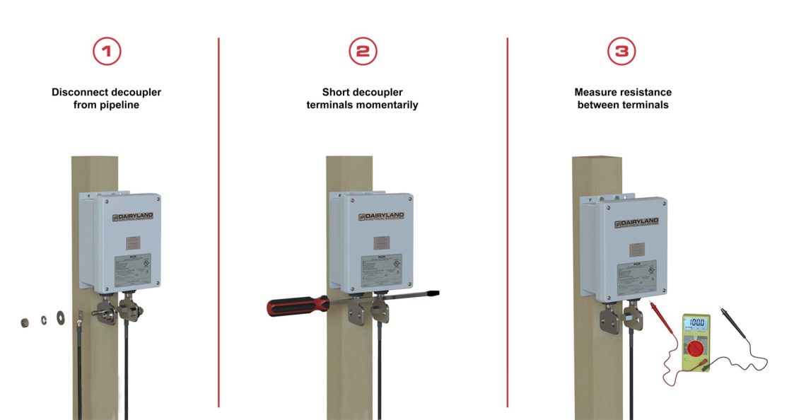
1) If the decoupler is in service, first disconnect one lead from the decoupler, so that the decoupler is electrically isolated.
- For pipe to ground installations, it is recommended that you disconnect the pipeline connection.
- For insulated joint applications, either lead may be used.
2) Next, momentarily short out the device terminals with a screwdriver or other convenient metallic tool to remove any residual charge that may be on the capacitor within the decoupler. Remove the tool before proceeding to step 3.
3) Connect a multi-meter, set to the lowest Ohms scale, across the terminals.
- If the decoupler is functional, the resistance will start at zero ohms and then slowly increase as the capacitor in the decoupler begins to charge from the multi-meter. You may discontinue the test at this point, as fully charging the capacitor may take several minutes, depending on the specific model, and it is necessary to observe this general response only briefly.
- If the product is failed, the reading will remain fixed and at a very low resistance value, typically a fraction of one Ohm.
Models OVP, OVP2
The models OVP and OVP2 block both AC and DC under normal conditions, before switching to the shorted mode. A direct test of the products can be made, and it differs from tests of the decouplers mentioned above.
1) Locate the device
2) If the device is in service, disconnect one lead from the device, so that the device is electrically isolated.
- If the device is functional, the resistance will immediately read a high value, typically hundreds of kilo-Ohms or greater
- If the device is failed, the reading will remain fixed and at a very low resistance value, typically a fraction of one Ohm.

Troubleshooting
Based on the extensive product history and design, it is not expected that Dairyland product failures will be encountered. If the above tests show the product to be functional, yet cathodic protection readings imply that a problem exists, consider the following possibilities:
Open circuit voltage too high:
If the CP voltage (or total DC voltage from all sources) is above the threshold voltage of the Dairyland device, the device will switch into the conduction mode for protection, which would affect CP readings. If this occurs, it is typically near a rectifier ground bed. Solution: select the same Dairyland product family, but with a higher threshold voltage.
OVP or OVP2 used where induced AC present:
The OVP and OVP2 are not designed to be used where induced AC is present. Installation with induced AC present will cause the device to switch to the conducting mode potentially impacting CP voltage. Switch to models SSD, PCR, PCRH, or PCRX to accomplish AC mitigation while blocking DC.
Insulating joint protected by decoupler fails radio frequency insulation test:
A Dairyland decoupler will appear as a short circuit to a radio frequency test device connected across an insulator. To test the insulator alone, remove the Dairyland device first, considering the safety issues discussed in this article. The Dairyland device can then be checked separately as discussed above.
Testing instructions for Dairyland products are often requested by customers wanting to verify decoupler operation. For a simple yet effective method of testing all Dairyland products follow the procedures outlined below.
Indirect Testing Method
Across product lines and applications, failures of Dairyland products are extremely rare. Often, a simple yet effective indirect test method is an adequate indicator of Dairyland product performance.
By design, Dairyland devices block CP current in their normal operating mode. Any device that is in its failed shorted mode will begin to conduct, resulting in a CP potential reading that is lower than normal. Therefore, reviewing your historical CP readings is a good indicator of product performance.
- Measure the cathodically protected structure pipe-to-soil potentials.
- If the readings indicate acceptable CP criteria and are in agreement with the trend of past readings at those locations, then the Dairyland device is almost certainly functional.
- If the CP potential readings are not as expected, a direct test of the decoupler should be performed to determine if the decoupler is shorted.
For instructions on performing a direct test please refer to: Dairyland Product Testing – Direct Test.