
Dairyland technical experts are occasionally asked how decoupler leakage current may affect potential readings of pipelines with no CP current applied. This article is intended to help answer questions related to the effects of DC leakage current through decouplers and how native or depolarized potential surveys may be impacted.
DC Leakage Current
Dairyland decouplers have a high resistance to DC current flow. There are situations where some DC current flow, known as DC leakage current, may be witnessed especially during native or depolarized potential pipeline surveys. For example, there may be a situation where a brand-new pipeline is being checked for its baseline potential voltage (i.e. native potential) to establish limits for use in the 100mV shift criterion from NACE SP0169. In this case, there may be some influence on the pipeline from the grounding wire connected through a decoupler for AC mitigation. This will be further explained in the paragraphs below.
This leakage current is typically in the single to double digit milliampere range. Graphs are presented in the Technical Literature for the products, and an example is shown here for the PCR decoupler:

These graphs reveal that as the DC voltage difference across the two decoupler terminals increases, there will be an increase in leakage current. Similarly, as temperatures increase, there will be an increase in leakage current. For example, in the graph shown above, a PCR decoupler with 2 V-DC across its terminals at 20 deg C (68 deg F) will have approximately 0.3 mA of DC leakage current. Note that the 65 deg C (149 deg F) is a graph to illustrate the upper temperature limits of the PCR.
This small amount of DC leakage can sometimes be noticed during normal operations. For example, at a site with active AC mitigation, the amount of AC amperage flowing through the decoupler is often measured. Note that small amounts of DC amperage may also be measured through the decoupler. A DC ammeter with a high resolution would typically be needed to see the DC amperage flow values and they will normally be less than 2 milliamps, with acceptable values reaching up to 20 milliamps.
Native Potential Surveys
Native potential surveys are used to get the open circuit potential for a metal placed into a soil using a reference electrode, such as a copper-copper sulfate reference electrode (CSE). The native potential is often captured after the pipeline is installed and allowed to acclimate to the surrounding soil conditions. There is no cathodic protection applied before the survey takes place. Another method to gather this baseline metal potential is to perform a depolarized survey. This means that cathodic protection was applied to the buried metal system, but is subsequently disconnected and the pipe is allowed to depolarize and return to it’s native state.
However, during the native potential survey the pipeline may be influenced if it remains connected to a decoupler with a grounding wire or another CP circuit on the positive side of the decoupler. Leakage current may impact expected pipe-to-soil readings of the pipeline with no cathodic protection applied, due to the small amount of DC leakage through the decoupler. The type of connected system can have varying effects on the native potential values on the pipeline as described below:
- Copper Grounding Systems: With a copper grounding system, the native potential of the copper is naturally at a less negative value on the galvanic series scale compared to a steel pipeline. Note that there is a very small differential in voltage potential between copper and steel, so the leakage current is very low and likely will not be noticed on the pipeline native potential surveys. Therefore, even if the decoupler remains connected between the pipe and the copper ground, there will be minimal impact to the values read during a native potential survey.
- Zinc Grounding Systems: A zinc grounding system presents a different scenario to a native potential survey as compared to copper. Since zinc is more anodic to the steel, there can be elevated pipe potentials found on a steel pipeline due to DC leakage current through the decoupler if it remains connected to the zinc grounding. This can be especially pronounced with new pipeline installations since the coating will be in pristine condition, resulting in extremely low amounts of current from the zinc to elevate the pipe potentials.
- Other CP Systems: The cathodic protection levels of a decoupled CP system can similarly affect the native potentials of the surveyed pipeline. The CP system will influence the native potential readings similar to how the zinc grounding system would behave, by increasing the potentials of the surveyed pipeline.
As a best practice, during native potential surveys, Dairyland recommends disconnecting all decouplers between the pipeline and the grounding circuit, and at locations where CP systems are isolated, such as isolation flanges. This ensures that the native potential survey will not be influenced by decoupled grounding or CP systems.
Leakage Current Values for Various Decouplers
For reference, the following table is provided to clarify the DC leakage current for various decoupler models and fault ratings. Note that this table covers the SSD, PCR, PCRH and PCRX decouplers only. For other Dairyland products, please consult Tech Support.
| Product Name | Threshold | Fault Rating | Leakage Current Amperes |
| SSD | -2/+2 | 1.2 kA | <5mA |
| 2 kA | <5mA | ||
| 3.7 kA | <5mA | ||
| 5 kA | <5mA | ||
| SSD | -3/+1 | 1.2 kA | <5mA |
| 2 kA | <5mA | ||
| 3.7 kA | <5mA | ||
| 5 kA | <5mA | ||
| PCR, PCRH | -2/+2 | 3.7 kA | <5mA |
| 5 kA | <5mA | ||
| 10 kA | <10mA | ||
| 15 kA | <20mA | ||
| PCR, PCRH | -3/+1 | 3.7 kA | <5mA |
| 5 kA | <5mA | ||
| 10 kA | <5mA | ||
| 15 kA | <20mA | ||
| PCRX | -4.5/+3.5 | 5.0 kA | <5mA |
| 10 kA | <10mA | ||
| 15 kA | <20mA | ||
| PCRX | -5.5/+2.5 | 5.0 kA | <5mA |
| 10 kA | <10mA | ||
| 15 kA | <20mA |
At Dairyland we know that the scale and scope of the Mega Rule updates continues to present challenges to pipeline operators. This article is the first in a series by our team (read articles two and three), designed to provide clarity amid the many new complexities of the Mega Rule. We also present solutions to some of the key challenges to enable informed decision making and compliance.
Background
The Mega Rule builds on and updates existing legislation designed to reinforce a risk management approach to the safety of natural gas transmission pipelines, natural gas distribution pipelines, and hazardous liquid transmission pipelines. Its third and final part became effective in 2023 with a compliance deadline of February 2024.
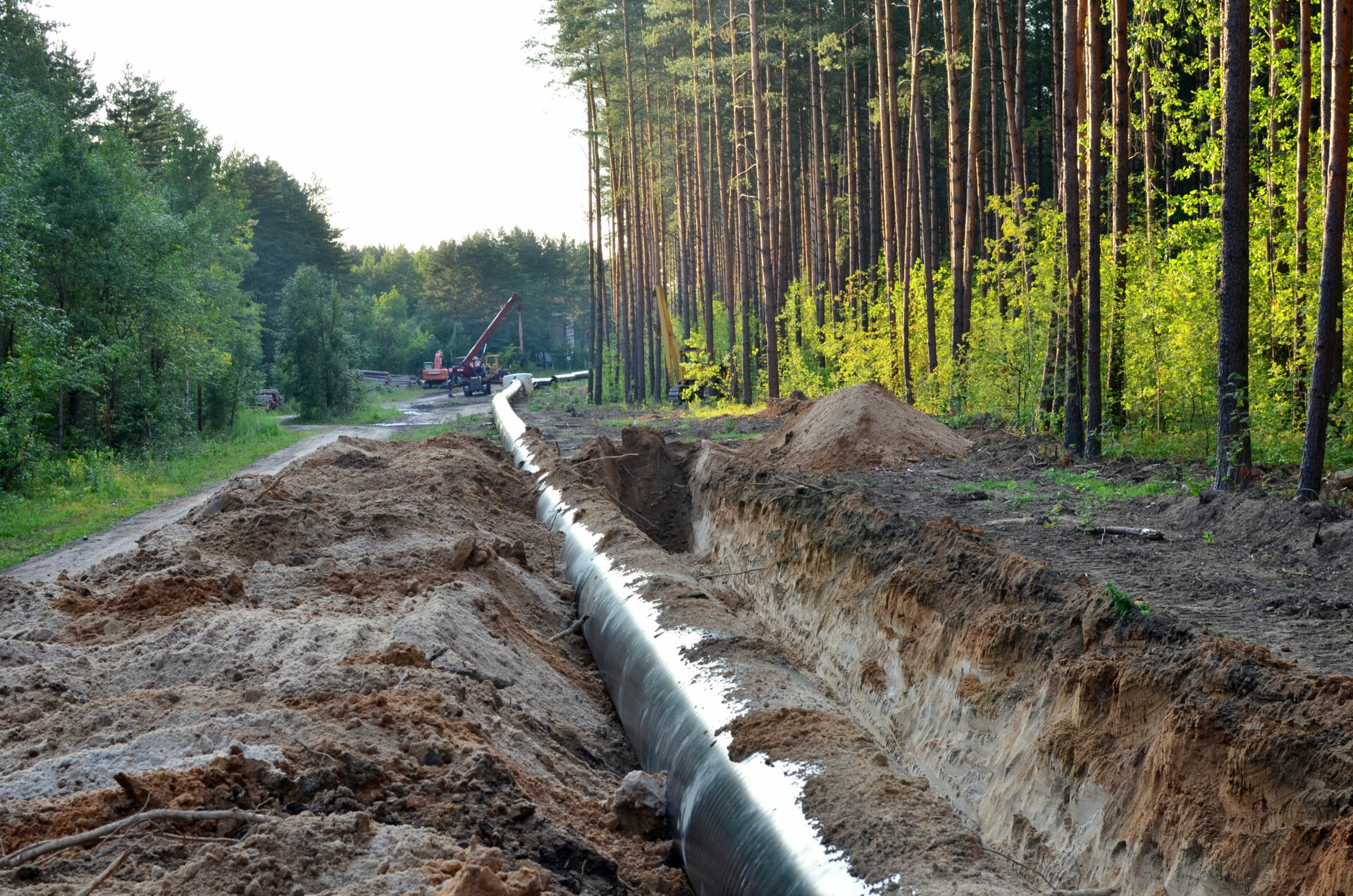
Natural gas pipeline under construction
Part 3 of the Mega Rule builds on its preceding parts that respectively tackle maximum allowable operating pressure (MAOP) and integrity management near high-consequence areas (HCAs), and the extension of federal safety requirements to onshore gas gathering pipelines with large diameters and high operating pressures.
It clarifies integrity management regulations from corrosion control requirements and repair criteria to post extreme weather inspection. It applies to onshore gas pipeline infrastructure spanning both HCA, and non-HCA.
Compliance with the Mega Rule in its entirety is firmly the responsibility of operating companies, the reality of which will vary depending upon the existing systems in place. Rule updates such as these can be challenging and implementing a compliant integrity management program has time and cost implications. However, Dairyland’s expertise and technologies can be put to work to ensure compliance, safety, and competitive edge.
Challenge #1: External Corrosion
To ensure compliance, pipelines must be monitored to determine cathodic protection (CP) Ievels. Definitively proving that a CP system is providing the degree of corrosion protection required is time-consuming and often inaccurate. Field testing has shown that interrupted surveys can sometimes be impacted by combinations of factors, such as pipeline coatings, soil resistivity, and the capacitance of traditional decouplers resulting in excessively electro-negative instant-off values. Nonetheless, where CP readings are below the required level, a close-interval-survey (CIS) is required to be completed. The CIS needs to be completed both upstream and downstream of the reading.
Any deficiencies must be remedied within a rule-stipulated window and following the completion of remedial action, an interrupted CIS must be undertaken again to ensure the pipeline potential readings are acceptable – incurring time and cost implications and increasing risk to personnel.
Solution #1: PCRX, The CIS Solution
The PCRX is the most sophisticated decoupler available globally. A solid-state, maintenance-free device, it is designed to simultaneously provide DC decoupling and AC continuity/grounding when used with CP structures. The PCRX provides typical decoupler functions with the additional benefit of electronically compensating for capacitance effects during interrupted surveys, including CIS. This prevents the device from contributing to errors in potential readings. The PCRX compensates to overcome capacitive effects, ensuring accurate and timely potential measurements. It does this without sacrificing the rugged over-voltage protection, AC mitigation, CP isolation, and safety grounding of Dairyland’s standard decoupling products.

With the Mega Rule impacting approximately 300,000 miles of existing onshore natural gas pipeline, and almost 20,000 miles of planned pipeline in the US, extending the life of these assets and building them in compliance with the regulations will require innovative technology and solutions.
In multi-purpose corridors where pipelines share the Right-of-Way (ROW) with high-voltage power lines, for example, corrosion risk is increased, as is safety risk to personnel. PCRX, however, will provide an effective grounding path that mitigates induced AC, while simultaneously maintaining DC isolation. This is possible because PCRX provides a low impedance to AC and high resistance to DC simultaneously. As a result, CP systems will continue to work efficiently, and pipelines plus personnel will be safe from undesirable AC interference.
With applications for retrofitting and new-build infrastructure, PCRX is proving to be an essential part of the modern CP system on pipelines and other protected structures for accurate CP readings while improving system performance and delivering the required safety protections.
Dairyland is here to help you make decisions on how our solutions can be applied to achieve Mega Rule compliance. Our technical support staff is ready to support you in a variety of ways, and always offer free personal consultations to help customers decide how to apply Dairyland solutions to your system.
Mega Rule Article 2: Interference Mitigation
Mega Rule Article 3: RMV Installation Best Practices
What is a DCVG Survey?
A direct current voltage gradient (DCVG) survey is a technique used to evaluate the effectiveness of corrosion protection systems on buried structures. This technique is used to analyze the coating condition and locate any coating “holidays” or coating defects on the buried pipeline.
In a DCVG survey, direct current (DC) is applied to the pipeline by using the pipeline’s impressed current rectifier or a portable power supply, and the voltage gradient is measured at intervals above the pipeline at the ground surface. The voltage gradient is measured by using two calibrated reference electrodes that are spaced a set distance apart. This measurement is the soil-to-soil potential difference and not the pipe-to-soil potential. Since most of the DC current will flow from the current source to a coating holiday, a voltage gradient will be present at a coating holiday and will appear as either current pick up or discharge.
Possible DCVG Survey Concerns with Standard Decouplers
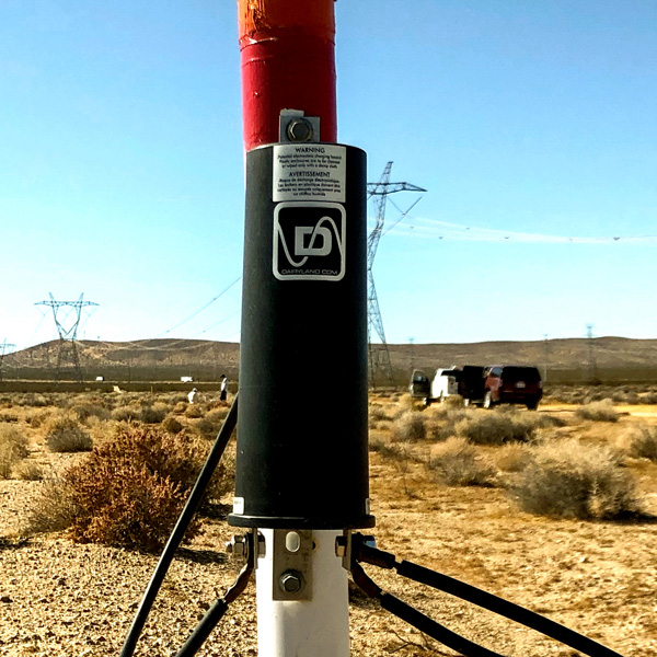
Dairyland SSD
During a DCVG survey, the impressed current rectifier or portable DC power supply is interrupted at a certain On/Off cycle similar to a Close Interval Survey (CIS). During the On cycle, the voltage gradient measured will be highest at the coating holiday. Conversely, during the Off cycle, the voltage gradient measured should not be present at that coating holiday as there is no DC current flow from the rectifier.
However, when standard decouplers (SSD, PCR, or PCRH) are installed nearby, this can affect the DCVG survey measurements and/or trigger a false reading with regards to coating holidays. This is due to the detection of a voltage gradient near standard decouplers and their connection to the grounding system. This may lead technicians to interpret this potential measurement as a large coating holiday and/or cause the operator to sway from the pipeline and follow the grounding system as it will be detected.
This voltage gradient is caused by the inherent capacitance of standard decouplers. These decouplers have a capacitor that is used to mitigate steady-state AC current from nearby HVAC lines. The capacitor holds a certain DC charge that looks like an uninterrupted DC source during the Off cycle of the survey. During the Off cycle, as the capacitor is discharged, it may still provide current to sustain the voltage gradient near the decoupler location and thus, may lead to an erroneous determination of a coating holiday.
The solution to this has been to temporarily disconnect the standard decouplers within the vicinity of the DCVG survey to remove this influence. However, this negatively affects the time to complete the survey and may increase the cost as well.
Solution For Faster DCVG Surveys
PCRX is Dairyland’s latest in solid-state decoupling technology. PCRX was introduced to the industry to virtually eliminate the capacitance issue found with standard decouplers. PCRX provides two main advantages over standard decouplers.
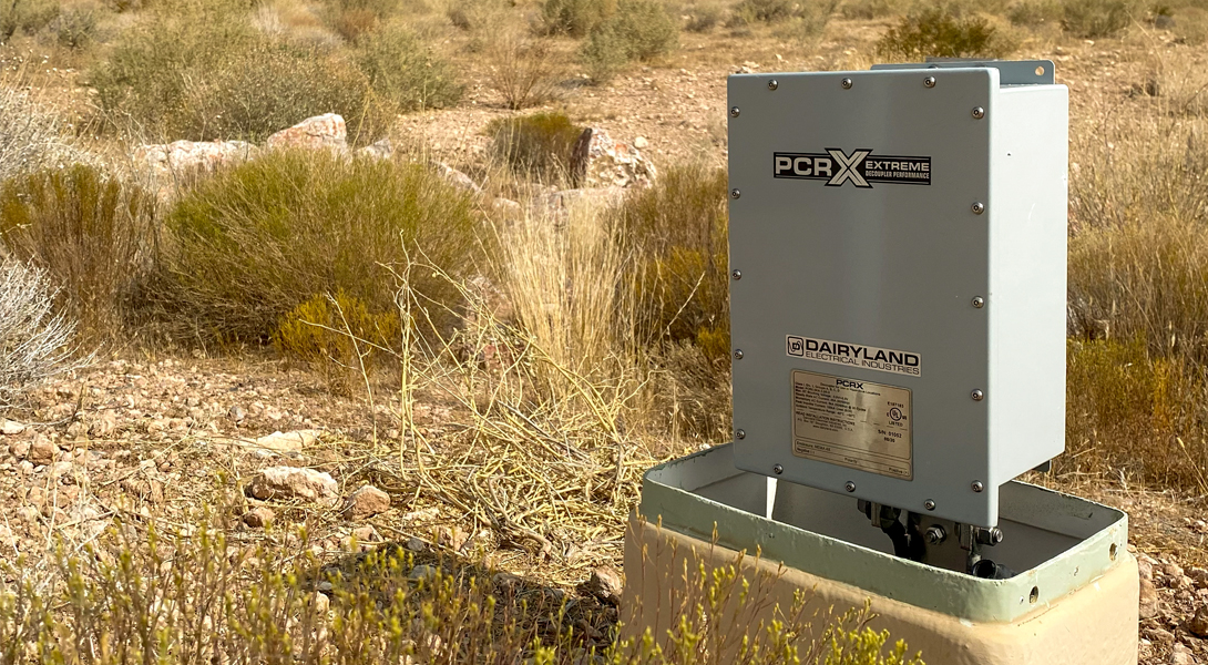
Firstly, it virtually eliminates the capacitive effects during the Off cycle, eliminating the voltage gradient and therefore, the possibility of an erroneous determination of a coating holiday. Secondly, there’s no need to disconnect the decoupler from the pipeline during the survey, always maintaining the connection to the mitigation system and keeping the pipeline grounded for over-voltage conditions. These benefits lead to safer and more efficient DCVG surveys.
We have a trained business development team ready to discuss your applications and product needs. Feel free to reach out to us to ask questions or consult on your needs – we are here to help!
Confirming effective cathodic protection on a target structure involves verification of accurate measured potentials to compare against industry criteria. This is often performed via an interrupted survey to remove certain errors, yet a capacitive effect on these readings may remain in place due to the presence of decouplers. The purpose of this paper is to inform the reader of the issues involved, focusing on testing methodologies applicable to evaluating decoupler effects in the field, leading to correct product selection and appropriate survey settings appropriate for a successful survey. This considers conventional Dairyland decouplers, the Dairyland model PCRX, and testing with no decouplers in place. Safety aspects are also discussed in the course of the testing regimes.
PCRX: A solution for Efficient, Accurate and Safe Interrupted Surveys
Interrupted surveys on protected structures such as underground pipelines with cathodic protection systems are often required. However, definitively proving that a cathodic protection system is providing the degree of corrosion protection expected can often be a time-consuming and error prone endeavor.
This paper is intended to educate the reader on some common issues that influence interrupted surveys, existing solutions to these issues, and a description of how the PCRX provides value in its groundbreaking approach to solving a key issue with interrupted surveys.
Introduction
Pipeline companies utilize cathodic protection to overcome external corrosion concerns. Owner interest in extending the life of the asset also generally includes addressing safety matters, which are often accomplished by solid-state decoupling products, such as those made by Dairyland Electrical Industries. Together, cathodic protection systems and decouplers address the multiple needs of corrosion prevention, isolation of CP from other structures, and safety grounding. Decouplers are a key part of the modern CP system on pipelines and other protected structures and both improve CP system performance and deliver required safety protections.
CIS Testing Interference
Corrosion prevention is efficiently provided by impressed current systems, and system effectiveness is regulated on most major pipeline systems by governmental authorities, such as the Department of Transportation (DOT) in the United States. Such compliance, as well as pipeline owner self-interest, is proven by various measurements, some of which include coating surveys and potential measurement surveys. A Close Interval Survey (CIS) is one such evaluation, accomplished by the user synchronously cycling all current sources, typically rectifiers, on and off at set frequent time periods. By examining the resulting potentials during on and off periods, the user can determine if compliance to corrosion criteria has been met, or remediation is needed in certain areas.
For safety and convenience, decouplers remain connected to the pipeline while the CIS is being performed, and in some cases the user may see unexpected results in the potential survey. Waveforms depicting the pipeline potentials over time may show a more slowly decaying potential during the off cycle, and likewise a slower response during the on cycle when the GPS interrupters turn the rectifiers back on. The resulting time-based absolute potential values during the off cycle therefore will not be as expected, appearing too electronegative. As cathodic protection compliance is based on such measurements, this can confuse the user and raise questions about their system operation.
Learn more about the CIS testing issue in this video
Decoupler Capacitance
Testing has shown that additional capacitance, typically from the decouplers but also from coating characteristics, slows the response of pipeline potentials. Decouplers, however, are essential safety devices and cannot be removed from the pipeline in most conditions. For example, the decoupler capacitance provides the needed low impedance to AC power frequencies that cause induced voltage to appear on pipelines near adjacent power lines. Industry standards, such as from the Association for Materials Protection and Performance (AMPP), limit the allowed voltage on pipelines for personnel and public protection, and Dairyland decouplers accomplish that function.
For perspective, users may consider why this is a problem observed in more recent years and not as much in the past. There are several factors that play a part in this. First and foremost, pipeline coating quality has improved dramatically, to the point that mere milliamps of CP current can protect many miles of pipeline. A pipeline that can be easily shifted in voltage for the purpose of cathodic protection can also be easily shifted due to any other source or effect. Stray direct current and induced alternating power frequency current are examples of other sources that can shift pipeline voltage quite effectively. Second, decoupler use has increased as users apply these devices for effective AC mitigation, lightning and fault protection, and DC isolation of grounding systems. This capacitance is additive to the coating capacitance. Finally, as CIS has become a more established technique and users look at resulting waveforms, awareness is increasing about this effect.
Addressing Decoupler Capacitance Issues
Users then often wonder how to address this dilemma. There are some techniques that may allow a user to compensate for this capacitive effect and still obtain acceptable readings. These include capturing the potential later in the off cycle period, extending the on and off time period durations, using IR-free coupons as an independent measurement, or in some cases disconnecting the decouplers (requiring a review to safely accomplish). Each of these approaches have pros and cons regarding accuracy, convenience, and safety. As decouplers are a normal part of the entire pipeline cathodic protection system, the intent is generally to leave the system intact as the current sources are all cycled together to obtain an acceptable CIS. Modifications to the CP system are discouraged, when trying to test the effectiveness of the installed system. Yet, in the end, valid absolute potentials are needed to compare to industry criteria for compliance. Dairyland has been deeply involved in research on the causes, effects, and possible solutions to this troubling and challenging problem.
PCRX – Extreme Decoupler Performance
Thousands of hours of research, development and field testing have resulted in a new innovation in decoupler technology.
Based on our company history of creating rugged and reliable solid-state devices to address demanding energy industry needs, the PCRX performs all of the expected Dairyland decoupler safety and isolation functions, and adds sophisticated solid-state systems to provide a correct CIS response. The PCRX’s active capacitance compensation renders it virtually invisible to changing potentials during a close interval survey, yet still accomplishes mitigation of steady-state AC induction as well as waits in anticipation of AC fault, lightning, or other events that require over-voltage clamping. Users who have become familiar with reliable Dairyland decouplers will enjoy those same isolation and safety features, along with overcoming CIS measurement issues in the new PCRX.
Field Testing Results
Extensive testing of the PCRX was performed over a period of years and at a number of pipeline locations. Sites with standard decouplers that had user-identified delays in CIS waveform response were selected as testing locations for the PCRX. Most sites surveyed had employed the decouplers for mitigation of AC induction from nearby power lines. Cycling the rectifiers on that pipeline or segment, using typical on-off periods, Dairyland engineers obtained “as found” waveforms with the decouplers connected. Next, waveforms were obtained with all decouplers disconnected from the pipeline, for comparison. Disconnection was done on a temporary basis using safe practices and utilizing AC voltage measurements for verification. After disconnection, waveforms generally showed a large improvement in response time, as expected. Next, the PCRX was connected in place of the existing decouplers, and waveforms were again obtained, resulting in a response that typically would mimic that of a pipeline with the decouplers disconnected. The pipeline potential waveforms below show a typical set of these three test conditions. Note how the PCRX response is essentially the same as with the decouplers disconnected.

The waveforms shown here were from a dry desert environment in the US southwest. The electrically continuous pipeline segment with the decouplers was 32 miles long, 24” diameter, with good quality FBE coating. A total of 8 existing PCR decouplers on this segment were evaluated for capacitive effects, producing the graphs shown, as they were compared to PCRX operation. Accurate results with the PCRX were achieved within 0.5 seconds, as seen above.
Conclusion
 Dairyland has provided a valuable new tool to the cathodic protection industry with the introduction of the PCRX. Able to respond quickly to cycling current sources, the PCRX allows efficient close interval surveys to occur, while retaining all CP isolation and over-voltage protection safety functions needed for pipeline operations. Adding to the complete line of Dairyland isolation and grounding technologies, the PCRX achieves substantial new improvements sought by the industry for years.
Interested in learning more? Download the full paper using the link to the right for an in-depth analysis of the PCRX’s performance.
Background
In some instances, decouplers such as the PCR and SSD, when installed on well-coated pipelines can affect OFF-potential readings during interrupted survey testing. The survey crew may witness irregular OFF-potential waveforms at or near where decouplers are installed. Most notably, the OFF values will be excessively electronegative as shown in the figure below.

It could be incorrectly concluded that the pipeline is well protected, however personnel should be aware that such OFF potential values may be in error. In some cases, such polarized values are not actually possible on protected steel. Instead of clean ON and OFF potential waveforms, personnel may observe curved and slowly changing waveforms that do not allow for a clear OFF potential reading. The reasons for this deviance have been investigated and are discussed in this video.
Resolution
The focus of this article is to help evaluate and resolve survey readings where OFF-potential waveforms are not reliable and decouplers are installed.
Following are steps that can be taken for possible resolution of response times that are unacceptable. This assumes that the user has established coordinated interruption of all other current sources and has captured waveforms of on and off response. Where present voltage capture settings are inadequate, consider the following alternative actions.
- For the same OFF period duration, capture the reading later in the cycle. For example, for a one second OFF cycle, take a reading at 700ms instead of 300ms.
- If the waveform is still decaying at the end of the OFF cycle, without the possibility of a valid potential measurement, set the ON/OFF interruption cycle to longer periods. The longer OFF period may allow valid voltage capture. Looking at the waveform after lengthening the cycle duration will show if this will be an effective option. Capture the pipeline potential at the earliest point in the OFF waveform that still provides an acceptable OFF value. Note: The use of a remote monitor at such locations is most helpful because the ON/OFF cycle and the off potential delay can be set remotely. Check with the monitor manufacturer for help to remotely set the ON and OFF interruption cycles, and how to extend the OFF potential delay read.
- If increasing the ON/OFF cycle time and increasing the OFF potential delay time has not provided acceptable data, then another option is to remove the decoupler from the circuit and perform the survey. The Dairyland Isolation Switch, an optional device that can be permanently installed in series with the decoupler, offers a safe and convenient way to remove the decoupler for interrupted surveys or any other purpose. Warning:For AC mitigation and certain other applications, removing the Dairyland decoupler from the circuit will leave the structure as an open circuit and increase the steady state AC voltage on the pipeline. The induced voltage on the pipeline may rise above the 15V AC safe level established by NACE guidelines. If the steady-state AC voltage rise is unacceptable, this may not be an option for the user. Once the decoupler is disconnected safely, proceed with the survey. You should now see OFF-potential waveforms that are more consistent with that of the other portions of the structure, as the decoupler and its effect have been completely removed from the circuit. When finished, it is important to reinstall the Dairyland decoupler into the circuit by placing the Dairyland Isolation Switch back into the normal operating position according to its instructions. Failure to do so will leave elevated AC voltage on the pipeline and at contact points.
- Should the potentials still not fall within an expected range then we suggest installing coupons to help achieve accurate potential readings. IR free coupons represent a low-cost option for obtaining polarized potentials because they avoid measurement errors due to current flow in the soil and are independent of the pipeline readings. Coupons could be used for any application where an independent reading is desired.
Product Solution
To address this interference issue that some users may experience, Dairyland has also developed the PCRX. Using sophisticated design techniques that represent the work of numerous leading experts around the world, the PCRX’s new camouflage technology renders it virtually invisible to interrupted survey testing, addressing the interference issue for users.
Like our other decouplers, the PCRX is a solid-state, maintenance-free device designed to simultaneously provide DC decoupling and AC continuity/grounding when used with cathodically protected structures, such as pipelines, tanks, and grounding systems. Commonly used DC decoupling of equipment from grounding systems, for AC mitigation projects, or other isolation and grounding applications, the PCRX provides safety grounding while also isolating your cathodically protected structure, improving CP system performance. Learn more about the here.
Should any questions remain about these procedures, please contact Dairyland Technical Support.
In this advanced training video, we’ll take a look at the interaction that can sometimes occur between decouplers and close interval survey measurements and discuss some options for rectifying this situation.