
Many user sites are formally classified as hazardous locations, according to various standards. Other sites may commonly have explosive vapors or gases present, but haven’t been identified as a “hazardous location” due to unfamiliarity with the classification requirements. Regardless, understanding hazardous locations is an important component for pipeline operators to factor in when applying decouplers to their systems. In this article, we’ll take a closer look at how sites are classified as well as its impact on product selection for your application.
What is a hazardous location?
Hazardous (Classified) Locations are defined in the US National Electric Code (NEC), Articles 500-505, and in other international standards such as the IEC, and describe requirements to ensure the safe operation of electrical products used in these locations.
Decisions on the classification of a particular site depend on several factors, most notably:
- Whether ignitable concentrations of flammable gases, vapors, or liquids are considered commonly present or uncommon
- The ease of ignition of the material, considering the gas or vapor type and the temperature of ignition
The classification system is summarized below, and compares the NEC Division and Zone methods, where the Zone system is comparable to that found in the IEC. Class I applies to gases, vapors, and liquids, and is broken down into the following areas.
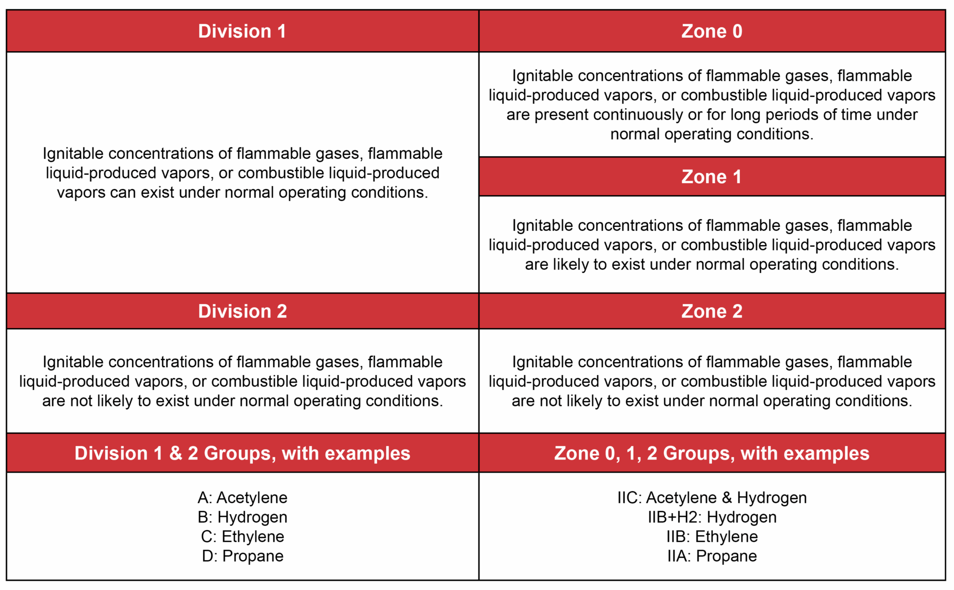
Often Overlooked
Admittedly, this area is not well understood by many pipeline operators, electrical inspectors, or federal regulators. Since the National Electric Code deals with electrical installations, most people don’t realize that this document also defines hazardous locations applicable to applying safety products within the corrosion industry.
A number of pipeline applications in which electrical products are used are non-traditional, hence electrical inspectors and pipeline operators may not identify that NEC 500-505 covers this installation. For example, an over-voltage protection device used on an insulated joint in a cathodically protected gas pipeline is not in a traditional electric circuit, yet it comes under the NEC hazardous location requirements and should be tested and certified by an independent laboratory for this purpose.
Throughout the industry, growing education on the topic of hazardous location is required. This education process involves:
- Identification of a site as a hazardous location
- Classification of the site according to the NEC guidelines
- Selection of electrical equipment that meets the NEC requirements
What if my site isn’t classified?
A report by the American Gas Association entitled “Classification of Gas Utility Areas for Electrical Installations,” number XF0277, expands on Articles 500-505 of the NEC, to further describe how specific gas pipeline facilities would be classified according to this system. Likewise, the American Petroleum Institute document RP-500 provides guidance to the petroleum industry. These documents help to apply the NEC requirements to equipment installations that are not otherwise obvious as being in a hazardous location.
Dairyland Products: Certified For Hazardous Locations
 A number of locations where Dairyland products are used could fall under an NEC-defined hazardous location. Typically, this would be a Class I, Division 2, Group D site, such as at an outdoor insulated joint, in a pipeline containing natural gas. Other sites may be classified as Class I, Division 1, such as fueling hydrant pits, underground vaults, or inside buildings, where an ignitable concentration is considered typically present. An electrical inspector may be the party that determines the classification of a given site, using the above criteria, and product selection must factor in the site classification.
Dairyland equipment is designed and tested to meet the specific requirements of defined hazardous locations primarily for safety purposes. During the certification process, third party testing laboratories such as Underwriter’s Laboratory (UL) and others, verify that devices used for over-voltage protection and grounding meet the appropriate requirements for each hazardous location classification. Additionally, manufacturers of products for hazardous locations have additional requirements to assure quality production and traceability. These systems are typically based on ISO9001:2015, and have additional ISO/IEC standards that apply, for a manufacturer to achieve full certification for ATEX and IECEx requirements. Dairyland is an ISO9001:2015 certified company ensuring robust quality systems throughout our organization.
Selecting the Proper Decoupling Products
Dairyland offers a variety of decouplers and over-voltage protectors that have been tested and certified to meet the various electrical requirements. The products are UL (United States) and C-UL (Canada) listed for:
- Compliance to hazardous location standards for Division 1 using the “flameproof” method of protection found in UL and CSA standards
- Compliance to hazardous locations standards for Division 2 using the “non-incendive” method of protection found in ANSI/ISA and CSA standards
Additionally, products have been certified by UL/DEMKO and UL for:
- Compliance to international standards (ATEX, IECEx) for Zone 1 using the “flameproof” method of protection found in EN and IEC standards
- Compliance to international standards (ATEX, IECEx) for Zone 2 using the “increased safety” method of protection found in EN and IEC standards
If your site is classified or otherwise treated as a hazardous location, then a product appropriate for this environment should be used, such as the following Dairyland models.
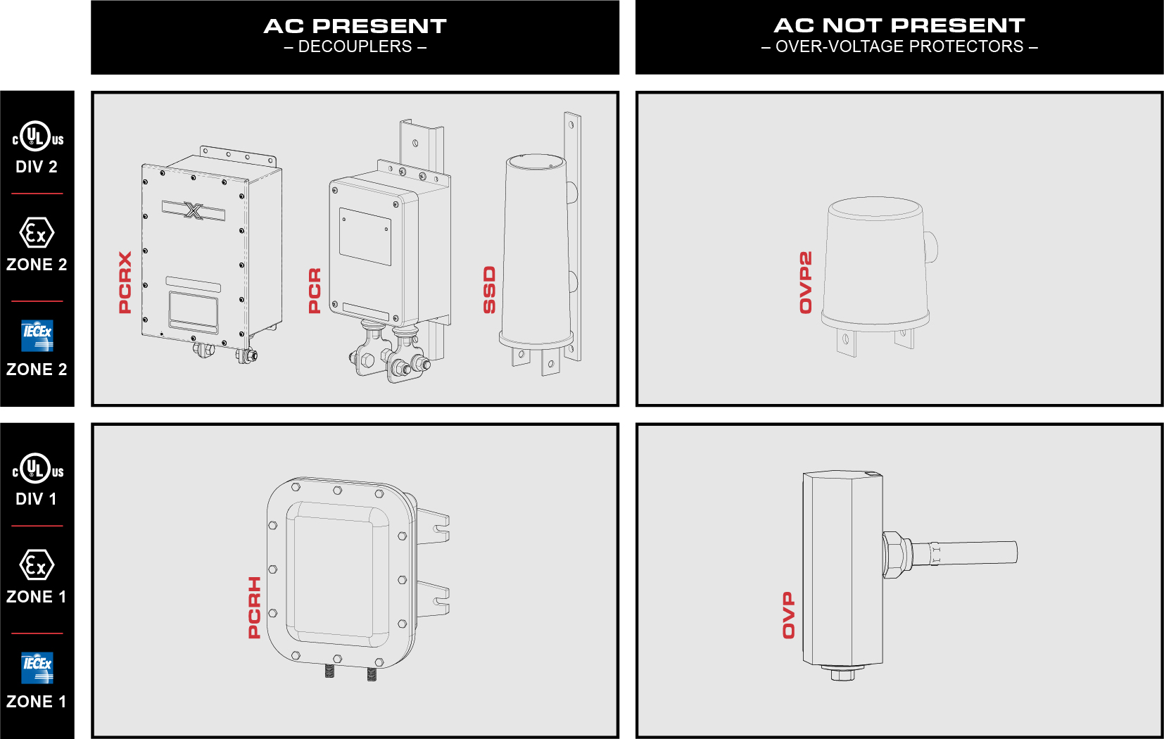
Have additional questions on hazardous locations or choosing the right decoupler for your application? Please contact our technical support team.
Any site with induced AC voltage at levels that require mitigation needs a product that provides AC grounding, without compromising the cathodic protection voltage. The device must be suitable for conducting steady-state AC current while blocking DC current, when connected between the pipeline and ground. Dairyland products provide continuous AC grounding for pipelines with induced voltage, while leaving the cathodic protection voltage unaffected.
For more information on this application, refer to: AC Mitigation
Measuring Induced AC
In order to properly select a product to use on your AC mitigation project, it is critical to know the amount of induced AC current present on the pipeline. Steady-state AC current can be measured using a clamp-on ammeter at a temporary bond established between the connection points — the pipeline and grounding system. The current value can then be compared to the Dairyland product ratings. The Dairyland product rating for steady-state AC current should exceed the values measured on-site.
Procedure:
- Using appropriate safety precautions, connect a temporary jumper between the pipeline and the grounding system.
- In the case of induced AC voltage at an insulated joint, where one side of the joint is grounded, connect the jumper across the joint.
- For underground transmission cable sheaths/casings, a grounding conductor will already be in place.
- Using a clamp-on AC ammeter, read the AC rms current flowing in the conductor
- If this value fluctuates daily or seasonally, several readings should be taken over time, selecting the highest reading for the rating of a Dairyland product.
- If several readings are not possible, adjust the measured value upward to reflect the higher seasonal changes. One major variable is the power line load current, so the adjustment could be determined from a comparison of the load current at the time of measurement to the power company’s maximum expected load current. This would require coordination with the power company to acquire these values. Lacking any ratio information, include at least some margin between the measurement and the device steady-state AC current rating. For underground transmission cable sheaths/casings, consider imbalance and harmonics.
Sizing and Installing a Decoupler
When selecting a Dairyland decoupler for your application it is critical to size the device properly for steady-state current. Standard decouplers like the SSD and PCR line of products have a 45A continuous rating, which is suitable for most applications. If higher ratings are required, ask Dairyland about our optional 80A rated devices.
Dairyland products have a set value where they transition from the DC blocking mode to the shorted mode, called the threshold, or blocking, voltage. The site’s maximum DC voltage and induced AC voltage, if any, should be known in order to select the proper Dairyland product rating. This measurement should be made between the same points to which the Dairyland device will be connected. For example, at an insulated joint, use a voltmeter to measure across the flange faces to determine the DC voltage difference. Likewise, at a pipeline in a station, measure between the pipeline and the grounding grid. Consider any stray DC voltage from rail or CP systems that will increase the needed product voltage threshold.
Key: The Dairyland product selected should have a DC blocking voltage that is greater than the measured DC site voltage for correct application.
AC Voltage
A common question from users is whether induced AC voltage in excess of the published Dairyland blocking voltage rating will put the device into conduction. The answer to this question is “No” because a Dairyland product such as the PCR, PCRH, SSD, or ISP is a low impedance AC path at the same time that it blocks DC current. AC induced voltage is immediately collapsed below the device threshold, and AC steady-state current flows through the device, without an effect on the cathodic protection voltage, when the proper steady-state AC current rating is selected.
A special case is the Over-Voltage Protector (OVP and OVP2), which blocks both DC and AC voltage up to a predetermined threshold level. This device should not be applied to sites with induced AC voltage, as it may put the OVP into conduction under normal conditions. It may be applied to such a site, however, if another Dairyland device, such as the PCR, is being used to first mitigate the induced AC. The DC plus peak AC voltage must always remain below the OVP blocking voltage for proper application.
Related issue: AC Voltage Mitigation
An AC fault results in the heavy flow of alternating current available from an electrical source during abnormal conditions. This current can be induced onto a structure without any metallic connection to it, such as in the case of pipelines in a common corridor with power lines. Current can also flow via conduction in grounding conductors, the soil, or other unintended paths back to the source, affecting cathodically protected structures.
Different applications involve varying levels of AC fault current, but in all cases some value of phase-to-ground AC fault current must be determined, even if only estimated. Some applications may not have notable AC fault current exposure, and the lowest standard product fault rating may be chosen. Applications are listed below, with suggested methods of determining the AC fault current for each.
AC Fault Current by Application
For a discussion of AC fault current data, choose your site description or application:
• Insulated Joint Protection
• AC Voltage Mitigation on Pipelines
• Decoupling Electrical Equipment (e.g. motor-operated valve)
• Decoupling Power Company Ground from User Site/Station Ground at the Transformer
• Decoupling Power Company Ground from User Site/Station Ground at User Panel
• Stray Voltage Mitigation at Farms (Primary-to-Secondary Isolation)
• Lead-Sheath or Pipe-Type Power Cable Decoupling from Substation Ground
• Blocking GIC/Transformer Neutral Decoupling
Contact Dairyland for assistance with any aspect of AC fault determination.
Exposure level: Since insulated joints are not usually directly tied via metallic connection to an AC faulting source, the fault currents are usually low to moderate. Higher exposure exists for insulated joints on pipelines serving power plants, or where the pipeline may become the metallic return path for fault current to the source.
Calculation method:
A) For insulated joints in a common corridor with power lines, where an AC mitigation study is being performed, the mitigation consultant can advise the expected or modeled fault current level.
B) For common corridor sites with no calculations or data available, typical values obtained by Dairyland from mitigation consultants in the past have indicated that a reasonable decoupler value would be 3.7kA. For cases where high fault currents are expected due to close proximity or other factors, select a higher product rating as appropriate.
C) For sites not in a common corridor with power lines, and not in metallic contact with AC fault sources, Dairyland product ratings lower than 3.7kA may be chosen.
AC Voltage Mitigation on Pipelines
Exposure level: Unless the pipeline has a direct, metallic connection to a power line grounding system (which is not recommended), the fault current is kept to moderate levels under most conditions due to the resistance offered by the pipeline coating and soil, and the limitations of the inductive coupling effect that produces this voltage. Direct metallic bonding of the pipeline to the transmission tower will greatly increase the exposure of the pipeline and coatings to fault current and lightning, and is not recommended.
Calculation method:
A) Manual calculations, or more commonly software analysis, are used to determine the fault current magnitude that can be picked up by a pipeline system. Specialized mitigation consultants can assist in performing this analysis.
B) An alternate method for estimation is to use a percentage of the power company’s maximum phase-to-ground fault current magnitude and time duration. This assumes that such data can be obtained from the power company, and is usually most useful if their fault current is relatively low, indicating that a modest decoupler rating may be acceptable. Higher fault values could indicate that an unnecessarily high decoupler rating is needed. From typical data obtained from mitigation consultants, a common range of fault values used from numerous past projects is from 3.7kA to 10kA.
Decoupling Electrical Equipment (e.g. motor-operated valves)
Also for: Ship-to-Shore Galvanic Isolation
Exposure level: The grounding conductor of an AC voltage system is designed to carry the full phase-to-ground fault current in the event of a fault (e.g. shorted conductors or motor winding failures). Placed in this grounding conductor, the Dairyland device would be exposed to the entire available fault current, and should be rated for such. Dairyland PCR, PCRH, PCRX, SSD, OVP, OVP2 and Marine Galvanic Isolator devices are all certified to US and Canadian standards for use in grounding conductors for electrical equipment.
Calculation method: The full available fault current in the AC circuit in question should be used. The methods for sizing include (in order of preference): A) comparison of the grounding conductor size to fault withstand graphs for cables, B) using the fuse or breaker clearing curve for the circuit in question, or C) calculation of the fault current at the transformer (worst case).
Each method is described below.
A) Comparison of the grounding conductor size to fault withstand graphs for cables
Device ratings can be indirectly estimated by comparison to the AC fault capability of the conductor used on the circuit of interest. This is based on the assumption that the conductor was originally sized correctly for the available fault current, and will generally result in a conservative selection. Locate the conductor size used on your circuit, then compare the current/time values in the withstand graph to the Dairyland device as shown in the figure below, choosing a product rating that approximates or exceeds the conductor rating.

Available Short-Circuit Currents for Insulated Copper Conductors (Ref NACE SP0177)
As this is an indirect method of fault sizing, it may be appropriate in some cases to have a Dairyland product rated below the conductor withstand value, if other factors, such as total conductor length, indicate that the fault current is substantially lower than the maximum conductor withstand. The following table summarizes the most common fault values and corresponding wire sizes.
| Wire Size (AWG) | Dairyland Product Fault Rating |
| #6 and smaller | 3.7kA |
| #4 | 5kA |
| #2 | 10kA |
| Larger than #2 | Contact Dairyland |
B) Comparison to fuse/breaker clearing curves
The next clearing device, such as a fuse or breaker, upstream (toward the source) of the circuit of interest can be compared to the Dairyland device ratings. The fuse or breaker “total clearing time” curve should be used, and a Dairyland device rating should be chosen to exceed these curve values. On a clearing curve graph, the Dairyland device ratings should appear to the right of the fuse/breaker clearing curve as shown in the example below.
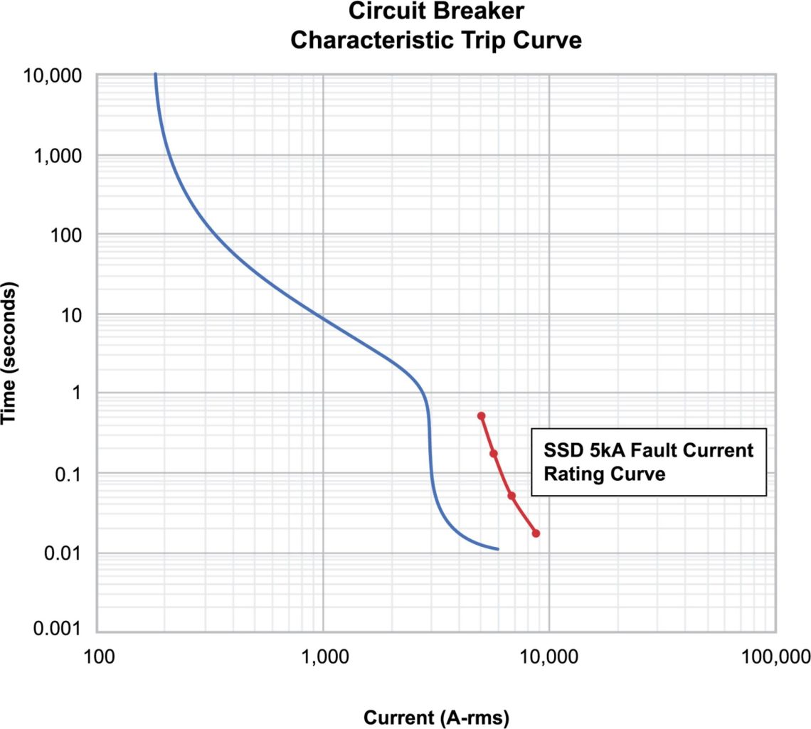
Example Circuit Breaker Trip Curve Compared to Decoupler AC Fault Current Rating
In the case of a ship where upstream breaker data is not known, the main shore power breaker on the ship could be used to obtain an estimate of the AC fault current.
C) Calculations based on the source fault current at the transformer
Unless the user has fault data for the exact circuit of interest, a conservative estimate can be achieved by starting with the fault current at the site transformer. If desired, further refinement can be done by calculating current reductions due to conductor impedance. This method is most useful for smaller electrical facilities; use at larger facilities may provide overly conservative values.
The maximum fault current available at the transformer terminals is determined by the following formula, using data from the transformer nameplate, which can be supplied by the power company or a site engineer.
Secondary full load current = Single Phase Transformer kVA / (Secondary kV)
OR
Secondary full load current = Three phase transformer kVA / (Secondary kV)(√3)
Then
Secondary fault current = Secondary full load current x 100 / Percent transformer impedance
This is the maximum fault current at the transformer, which will be reduced by conductor impedance. This reduction can be estimated using wire characteristics for various cross-sections and lengths.
Decoupling Power Company Ground from User Site/Station Ground at Transformer
Exposure level: A Dairyland device connected as the sole bond between a power company grounded neutral system and the secondary grounded neutral system at a station or other site with cathodic protection will be exposed to, and should be rated for, the full primary fault current from the power company distribution system.
Calculation method: The primary phase-to-ground fault current (magnitude and duration) at the transformer should be requested from the power company’s distribution engineering department. If this is not available, the fuse clearing curve can be requested from the utility. A Dairyland product rating should be chosen that exceeds the “total clearing time” of the fuse or breaker. A graph of current versus time values should result in the Dairyland device to the right of the clearing device curve.
Decoupling Power Company Ground from User Site/Station Ground at User Panel
Exposure level: A Dairyland device connected as the sole bond between a power company grounded neutral system and the secondary grounded neutral system at a station or other site with cathodic protection will be exposed to, and should be rated for, the full secondary fault current from the power company transformer.
Calculation method: Unless the user has fault data given to them by others, the secondary fault current available at the terminals of the transformer should be determined. This can be calculated from the transformer nameplate data. If desired, further refinement can be done by calculating current reductions due to conductor impedance, for the distance between the transformer and the decoupler at the panel.
The maximum fault current available at the transformer terminals is determined by the following formula, using data from the transformer nameplate, which can be supplied by the power company or a site engineer.
Secondary full load current = Single Phase Transformer kVA / (Secondary kV)
OR
Secondary full load current = Three phase transformer kVA / (Secondary kV)(√3)
Then
Secondary fault current = Secondary full load current x 100 / Percent transformer impedance
This is the maximum fault current at the transformer, which will be reduced by conductor impedance. This reduction can be estimated using wire characteristics for various cross-sections and lengths.
Stray Voltage Mitigation at Farms (Primary-to-Secondary Isolation)
Exposure level: A Dairyland device connected as the sole bond between a power company grounded neutral system and the secondary grounded neutral system at a farm or residence will be exposed to, and should be rated for, the full primary fault current from the power company distribution system.
Calculation method: The primary phase-to-ground fault current (magnitude and duration) at the transformer should be determined by the power company’s distribution engineering department. If this is not available, the transformer fuse clearing curve can be examined. A Dairyland product rating should be chosen that exceeds the “total clearing time” of the fuse or breaker. A graph of current versus time values should result in the Dairyland device to the right of the clearing device curve.
Lead-Sheath or Pipe-Type Power Cable Decoupling from Substation Ground
Exposure level: A Dairyland decoupler is typically used at each end of a power cable circuit, between the sheath/pipe and substation grounding system. As the sole grounding path, the Dairyland device may see the full phase-to-ground fault current on the transmission system, and should be rated for this value.
Calculation method: As this would likely apply only to transmission cable systems owned by power companies, the power company can turn to their transmission engineering department for the phase-to-ground fault current magnitude and duration. These values have already been modeled for the transmission system, and are readily available. Choose a Dairyland device AC fault rating that exceeds the modeled system fault current and time duration. Dairyland publishes 1, 3, 10, and 30 cycle current values to assist with product selection. Interpolation between published values can be done – contact Dairyland for additional guidance.
Blocking GIC/Transformer Neutral Decoupling
Exposure level: The grounded transformer neutral that is affected by GIC (Geomagnetic Induced Current) or DC currents can have a Dairyland decoupler placed in series in the bond/neutral. This subjects the decoupler to the full fault current available in the neutral.
Calculation method: The full available fault current should be used, which can be obtained from the power company substation or transmission engineering department for the neutral (phase-to-ground) fault current magnitude and duration. These values should be readily available. Choose a Dairyland device AC fault rating that exceeds the modeled system fault current.
All solid-state DC decouplers and Over-Voltage Protectors have specific voltage threshold ratings. For successful application, it is important to understand these ratings and how they can affect your CP system. This article will use specific examples to explain how to select the proper voltage threshold for your application. You can also utilize our Voltage Threshold Simulator to ensure your selection of device and voltage threshold rating do not cause the device to go into conduction during normal operating conditions.
Decouplers and Over-Voltage Protectors are designed to block the flow of low voltage DC current yet provide safety grounding protection in the event of AC faults or lightning. The voltage threshold (also known as the blocking voltage) of the device determines the voltage across the terminals at which the device transitions from blocking mode (DC isolation) to conduction mode (safety grounding). When the voltage across the device terminals exceeds the voltage threshold, in either polarity, the device will conduct both AC and DC current. Once the voltage drops below the voltage threshold, the unit will return to blocking mode.
Common threshold voltage ratings are written as -2/+2 or -3/+1. This is the voltage range (i.e., between -2V and +2V) within which the device blocks DC current. The table below gives examples of how threshold voltage ratings are specified in the model number of different Dairyland devices.

Though -2/2 and -3/1 are typical ratings, some devices are also available with higher voltage thresholds for use in applications with higher CP levels.
How to determine the proper voltage threshold rating
To determine an appropriate threshold rating, measure the DC voltage across the points where the device will be connected during normal operating conditions. This voltage can also be estimated by calculating the difference between the pipe-to-soil potentials from each side of where the device will be connected. In either case, record the voltage as the negative terminal voltage with reference to the positive terminal voltage. This voltage should be within the range of the device voltage threshold rating.
Although decouplers are designed to provide low impedance for AC current, there will be some small AC voltage drop across the device if any AC current is present, and it is important to account for this added voltage drop when selecting a voltage threshold rating. For example, for SSDs and standard PCRs, the device impedance is approximately 0.010 Ohm at 60 Hz and 0.012 Ohm at 50 Hz. Induced current of 10 Arms flowing through an SSD at 60 Hz will create 0.10Vrms (0.14 Vpeak) of AC voltage drop across the SSD. Be sure to add the peak value of this AC voltage drop to the DC voltage difference expected across the device. Note that at the maximum rated steady state current for SSDs and standard PCRs of 45Arms (64Apeak), this voltage drop due to AC could be as high as 0.64V at 60 Hz (0.76V at 50 Hz).
Examples
Scenario 1:
Both sides of an isolation joint are protected by CP. The P/S (pipe-to-soil voltage) ON reading for one side of the joint is -1.35V. The opposite side of the joint has an ON reading of -1.05V, resulting in a voltage difference of -0.30V. There is no induced AC measured on the pipe.
Since the nominal DC voltage of -0.30V across the joint is well centered within both -3/+1 and -2/+2 ranges, either rating would be appropriate. This is illustrated below in the graph of voltage vs. current for a decoupler with -2/+2V rating. Note that the DC leakage current through the decoupler is less than 3 mA within the voltage threshold range.
Typically, however, a symmetrical device is used for the situation where CP is present on both sides of an isolation joint since the difference in potentials across the joint is typically close to zero.
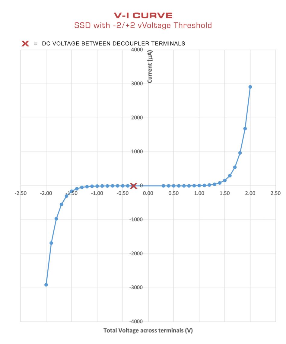
Total Voltage expected across device terminals = VDC + VAC
VDC = V1 – V2
V1 = -1.35V
V2 = -1.05V
-1.35 – (-1.05) = -0.30V
VAC = 0
VDC + VAC = -0.30 + 0 = -0.30V
This is well within the threshold rating of a -2/+2 decoupler.
Scenario 2:
The cathodically protected side of isolation joint P/S ON reading is -2.45V. The opposite side of the joint is grounded to copper with a corrosion potential of -0.34V. There is no induced AC measured on the pipe.
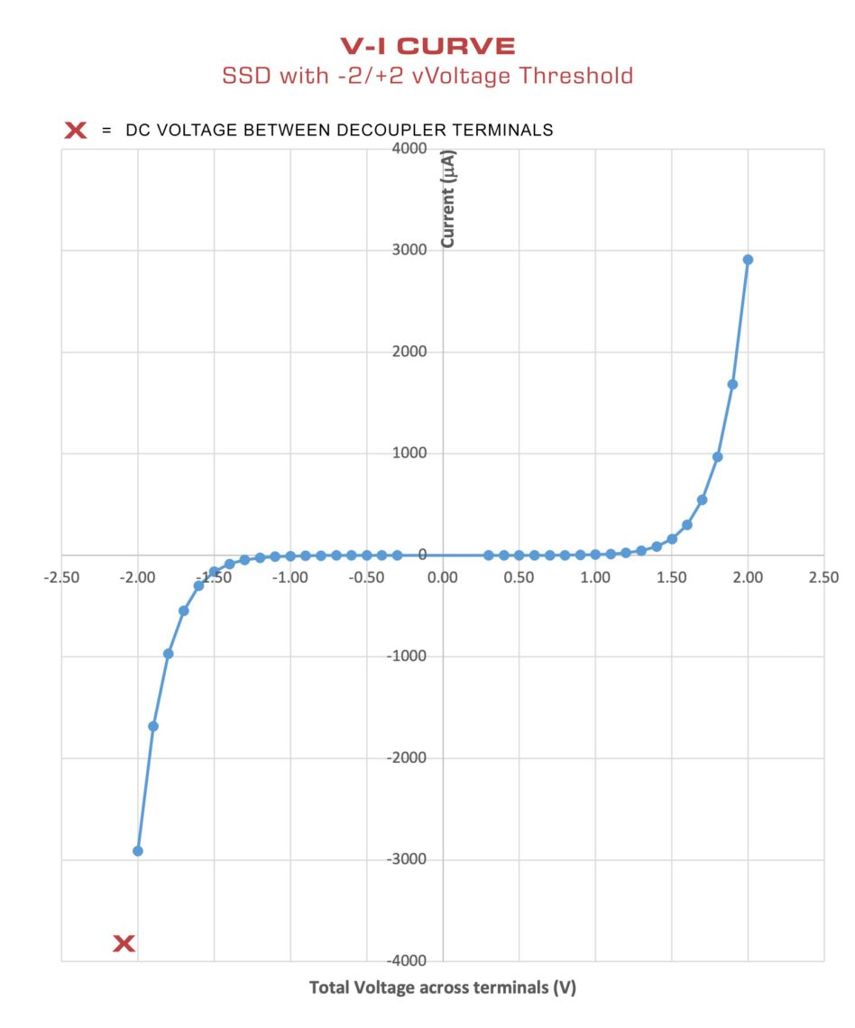
The DC voltage difference is -2.11V which exceeds the negative threshold of a -2/+2V rated device. As shown in the graph below, using a device with a -2/+2 voltage threshold in this application would cause the device to be continuously in conduction and so short out the structure to ground.
Total Voltage expected across device terminals = VDC + VAC
VDC = V1 – V2
V1 = -2.45V
V2 = -0.34V
-2.45 – (-0.34) = -2.11V
VAC = 0
VDC + VAC = -2.11 + 0 = -2.11V
This exceeds the negative threshold of a -2/+2 device and would result in a continuous short to ground.
Recommendation: Select a device with a threshold rating of at least -3/+1V. See the graph below for the new, acceptable result if a -3V/+1V device were used instead of a -2/+2V unit.

Scenario 3:
Decouplers to be installed to isolate a pipeline from an AC mitigation grounding system. The pipeline P/S ON reading is -2.25V. The copper mitigation wire reading is -0.35V. The maximum steady state induced AC current flowing from the pipe to the mitigation wire at this location is 10Arms at 60 Hz.
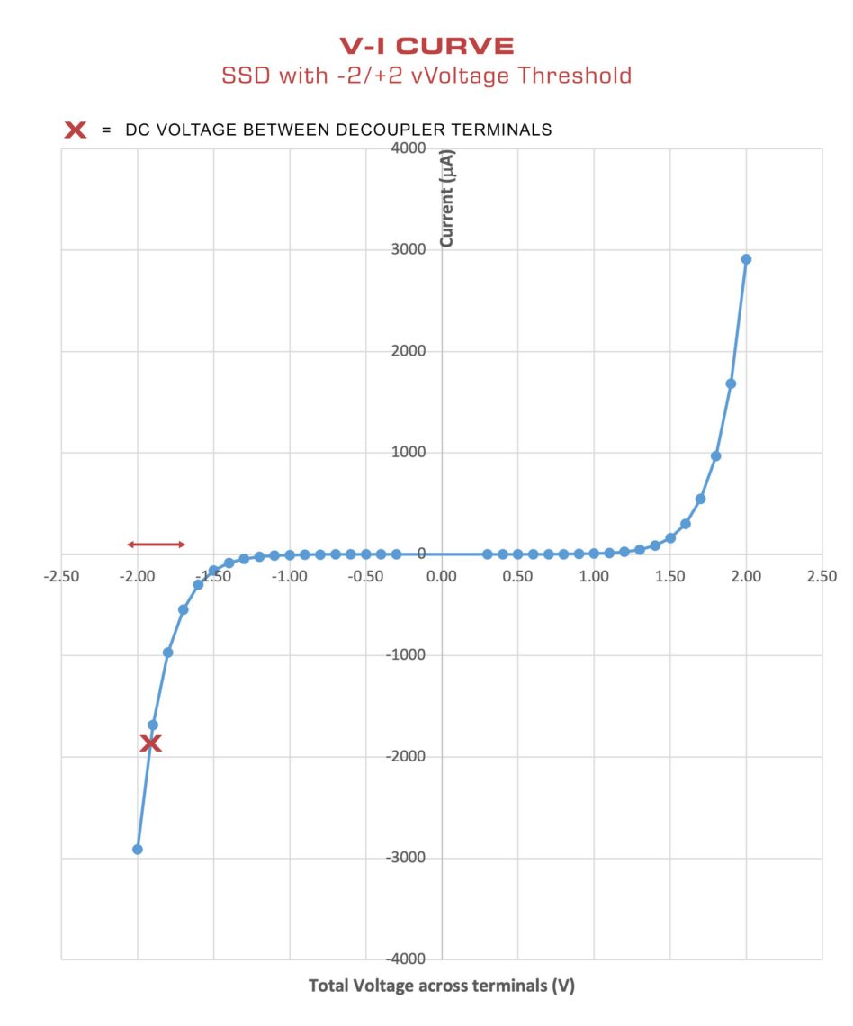
The DC voltage difference is -1.90V, which is close to exceeding the negative threshold of a decoupler with a -2/+2V threshold. The additional voltage drop due to the induced AC current is 0.10Vrms (0.14Vpeak). Combined, the DC and AC voltages across the decoupler will cycle between -2.04V and -1.76V at 60 Hz as shown in the graph below. In this case, the decoupler would cycle in and out of conduction at 60 Hz.
Total Voltage expected across device terminals = VDC + VAC
VDC = V1 – V2
V1 = -2.25V
V2 = -0.35V
VDC = -2.25 – (-0.35) = -1.90V
VAC = Current * Decoupler Impedance
Current = 10Arms = 14.14Apeak
Impedance = 0.01 Ohm at 60Hz
VACPeak = 14.14Apeak * 0.01 Ohm
VACPeak = 0.14Vpeak
Vtotal = VDC + VAC = -1.90 +/- 0.14 Vpeak
Vtotal = -2.04V to -1.76V
This total voltage exceeds the negative voltage threshold of a -2/+2 rated device and would cause the device to cycle in and out of conduction at 60 Hz.
Recommendation: Select a decoupler with a threshold rating of at least -3/+1V.
Device Operation with a Given Threshold Rating
The device should always be installed with the negative terminal connected to the more electro-negative structure – typically the cathodically protected structure – and the positive terminal to the more electro-positive structure, often a grounding system without cathodic protection. You can learn more about proper configuration of the terminals in the article Polarity Matters.
With this arrangement, the structure connected to the negative terminal will be limited to a voltage equal to the negative threshold rating relative to the positive terminal/structure. Likewise, the same negative structure cannot rise in voltage above the positive threshold, relative to the positive structure. This keeps one structure close in voltage to the other structure, regardless of which was affected by an over-voltage condition.
Rule of Thumb for Proper Threshold Selection
- In most situations where both terminal connection points are cathodically protected, a threshold rating of -2/+2 will be an acceptable choice. If one side has a CP reading that is higher than normal, then a -3/+1 or higher value should be selected.
- For isolation joints with only one side receiving cathodic protection, a threshold rating of -3/+1 is usually appropriate.
- For AC mitigation projects with copper grounding systems, a threshold rating of -3/+1 is usually appropriate. For AC mitigation systems with zinc grounding systems, a -2/+2 threshold rating is usually appropriate.
- In the case of isolating electrical equipment on a CP system from a copper grounding system, a threshold rating of -3/+1 is typical, since copper is notably shifted on the galvanic series of metals compared to most protected structure potentials.
- When decoupling an entire facility with CP from a power utility grounding grid, the expected potential difference between two grounding systems is often small, and within the rating of -2/+2, however a -3/+1 threshold is also a safe choice.
PCRX Voltage Threshold Selection
The voltage threshold ratings for the PCRX differ slightly from other devices. See the PCRX Technical Literature for a detailed description of how to select the threshold voltage for a PCRX.
If selecting the proper threshold rating is in question, please contact Dairyland’s technical support.
Wherever pipelines or other metal structures are in close proximity with high voltage AC transmission lines, there exists the potential for the structure to experience AC faults. An AC fault occurs when there is a short between one of the phase wires and the tower or ground. The ground fault current flows through the earth surrounding the tower and possibly onto nearby buried pipelines, storage tanks or other structures. Any decoupler or over-voltage protector connected to these structures must be able to reliably carry the fault current that can be experienced at that location without failure.
To address AC fault concerns, Dairyland decouplers and over-voltage protectors are designed, tested and third-party certified to ensure reliable, repeatable operation during AC faults. Figure 1 shows the results of an AC fault test performed on an SSD-2/2-5.0-100.

Third-party verified tests ensure product performance meets the stated manufacturer claims, and are valuable confirmation to users. Products that have not been third-party certified frequently do not perform to their stated values and often experience failures leading to high replacement costs and safety issues.
In addition to verified fault current ratings, Dairyland products are certified “fail-safe” devices, providing an important safety redundancy. Our verified fault current ratings lead to rugged product performance and very few failures, but in the unlikely event a product does fail, it always fails closed. This failure mode is an important safety feature when considering personnel protection. Decoupler users throughout the industry should look for both certified fault current ratings and fail-safe operation in order to ensure product performance, long life and safety. Existing products on the market with inadequate characteristics and uncertified designs have been observed to arc and fail open during AC fault exposure – a totally unacceptable condition with severe risks to industry personnel and equipment.
Sizing for Fault Current
Dairyland products are available in a range of AC fault current ratings, as seen, for example, in Figure 2 for the SSD product family.

When selecting the model for an application, users should take into account the available fault current exposure their structure might see during a fault event. Note that the fault current capability for each device is conservatively rated at 30 cycles (i.e., 0.5 seconds for 60 Hz and 0.6 seconds for 50 Hz).
Learn more about sizing for fault current: Determining AC Fault Current
It can be difficult to know which ratings or classifications are needed when determining which Dairyland product is right for your application. Dairyland offers a wide range of product families with features that work within a diverse set of applications. This article is meant to help you determine which product is right for your needs. If you have any questions, please contact techsupport@dairyland.com.
Decoupler or Over-Voltage Protector?
Decouplers are commonly used to isolate cathodically protected structures from other equipment grounding systems, enhancing the cathodic protection system’s performance. They also perform a function of safely grounding induced AC (alternating current), fault current and lightning. Over-Voltage Protectors provide the same DC (direct current) isolation and protection from fault current and lightning, but are not designed to address induced AC.
The first question to ask when selecting a Dairyland product is whether there is (now or potentially in the future) any induced AC voltage present. Induced AC commonly occurs on structures near overhead powerlines. If the answer is yes, or you are unsure, select a decoupler to address any present or future issues with induced AC.
What Hazardous Location Classification Do You Have?
Commonly used products like the SSD, PCR and PCRX are designated as Division 2 or Zone 2 products. This is a common hazardous location designation, where explosive gases and vapors are not typically present.
Sites can also be designated as Division 1 or Zone 1, where explosive gases and vapors are commonly present. Dairyland’s PCRH and OVP are both rated for Division 1 and Zone 1. If you need help identifying which product is appropriate for your specific site conditions, contact Dairyland. You can also learn more about hazardous locations here.
Use the chart below to identify which product is appropriate for your specific site conditions.

Choosing a Specific Decoupler Model
If you have determined that your application calls for a decoupler, proceed with selecting your specific model number by using a product’s configuration tool on the Dairyland website or by contacting customerservice@dairyland.com. Dairyland’s full lineup of decouplers offers a range of fault current ratings, steady-state current ratings, and additional features. Using the chart below, you can evaluate the available options for each decoupler.
Notably, the PCRX line is the only product line to feature active capacitance compensation technology, designed to eliminate the influence of decoupler capacitance on instant-off measurements during interrupted surveys. You can learn more about identifying sites that may require the PCRX here: When do I need a PCRX?

Choosing Decoupler Ratings
Several criteria are required to select the proper decoupler ratings. Dairyland technical support teams are always willing to assist you with selecting the proper model numbers for your application. Additionally, we have numerous articles available to assist you.
Measuring Induced AC
Determining AC Fault Current
Determining Maximum DC Voltage
Understanding Voltage Threshold Ratings
- Previous Page
- Page1
- Page2