
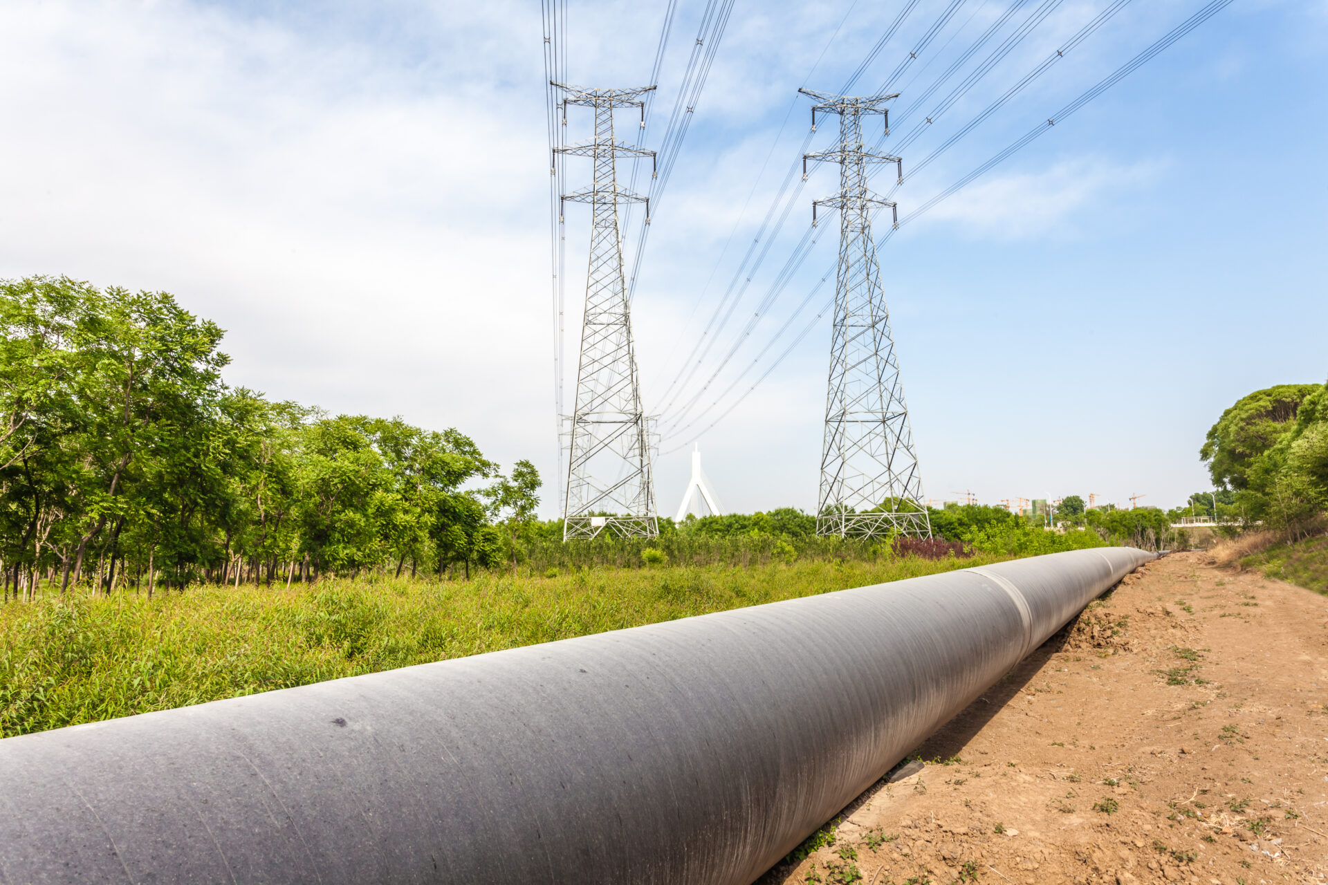
With increasing frequency, corrosion industry professionals are being asked to address induced AC that occurs when pipelines are located in common corridors with overhead powerlines. When working on AC Mitigation projects, one of the primary goals is to minimize voltage levels between two points of contact. Not only is this crucial for personnel safety, but it’s also important for keeping your equipment protected. Over-voltage differences could result from a single event, such as a utility fault or lightning strike, or be constantly present due to induced AC from nearby High Voltage AC (HVAC) lines.
Worker Safety
These voltage differences can reach unsafe levels and create a significant worker safety risk. Personnel can make contact between two points having a voltage differential at an isolation flange (touching each side simultaneously), between a pipeline and a ground, between two grounding systems, as well as a single grounding system where a voltage gradient could exist in the earth.
If a person makes contact between two points with a high voltage difference that are not referenced to each other, there can be a significant risk of injury or death. According to AMPP SP0177, as well as IEEE Standard 80 “Guide for Safety in AC Substation Grounding”, a maximum of 15 Volts AC is the safe “let go” criteria, which means operators must mitigate the risk to below these levels to adequately protect workers.
Equipment Protection
Personnel safety is not the only risk. High voltage differences from lightning and AC faults could also cause damage to the equipment itself, or the isolation materials used at isolation flanges, causing damage to the flange components. Just like the criteria for personnel safety, equipment and products have voltage limits that need to be mitigated in order to protect those items and prevent costly damage to system components.
Protect Personnel and Equipment – Use a Decoupler

A decoupler plays an integral role in any AC mitigation design by helping to address concerns for both worker safety and equipment protection. While grounding is required to address safety and equipment concerns outlined above, isolation is required to maintain an effective CP system. Decouplers are appropriately rated to handle over-voltage conditions while simultaneously providing CP system isolation, protecting the integrity of your CP while also protecting your personnel and equipment.
Don’t Forget! Important Safety Considerations
Effectively utilizing decouplers in your AC mitigation applications will help to minimize voltage differences to safe levels for both personnel and equipment. Therefore, consider the following important safety tips:
Address Lightning Concerns
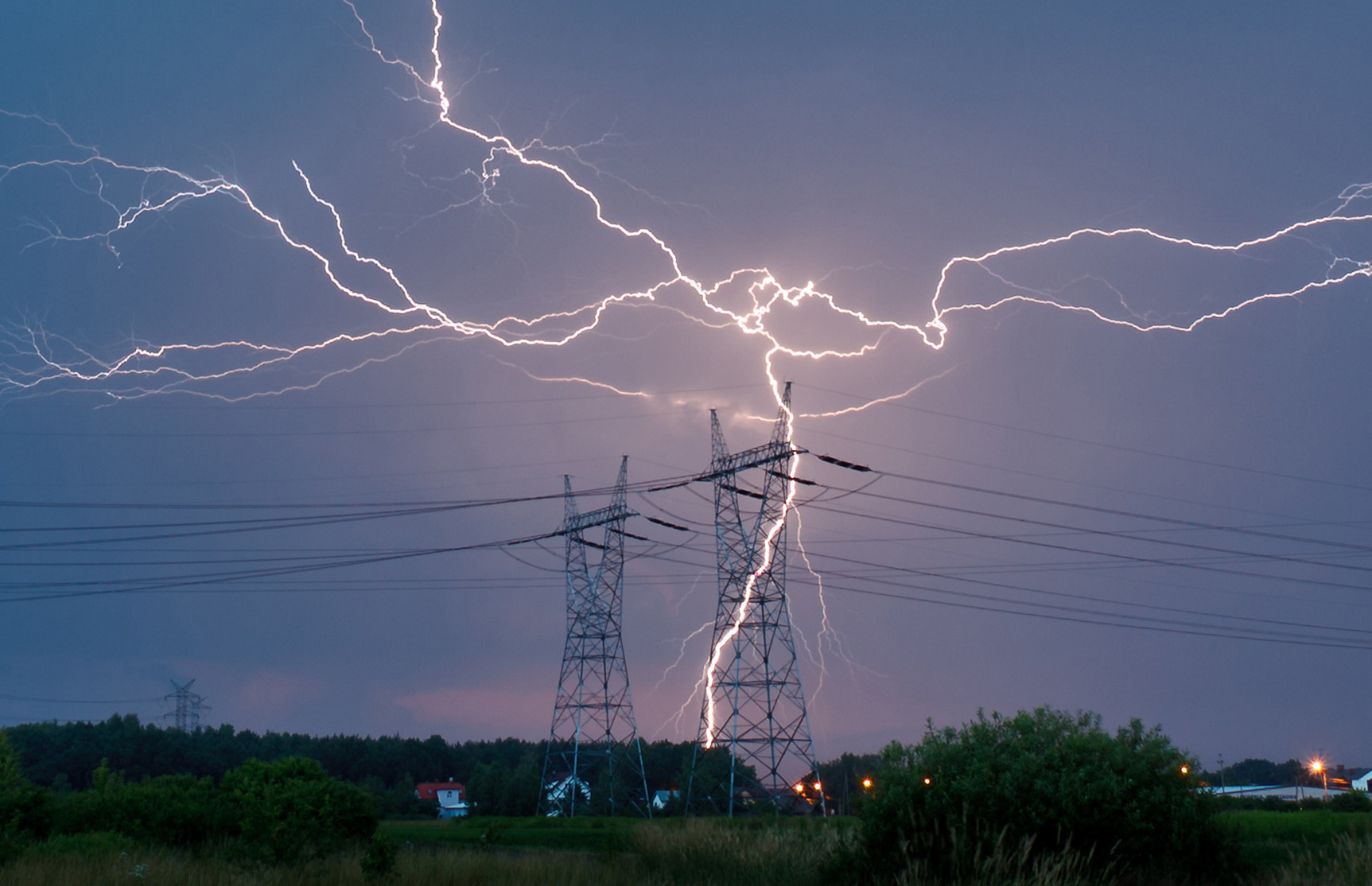
Lightning strikes are very fast, violent over-voltage events. Protective products need to be capable of handling the forceful, fast nature of a lightning strike or they could fail in catastrophic fashion. All Dairyland products have a significant lightning current rating, ensuring continued operation after a lightning event. In addition, the installation method of a decoupler is also critically important.
Safety Tip #1 Keep Conductor Lengths as Short as Possible
Conductor length used to connect a Dairyland decoupler is a critical component of proper installation. Conductors with lightning current flowing through them will have a significant voltage drop along the length of the conductor. Conductors have an inherent inductance, and the greater the inductance the higher the voltage spike during the event, making it critical to keep the conductors as short as possible. Not familiar with inductance? Read more about it here: Conductor Length Effects Upon Over-Voltage Protection From Lightning Conditions
When dealing with buried pipelines, it may be difficult to keep lead lengths as short as possible, which could limit the use of decouplers in this scenario. However, when dealing with above-grade isolation joints and gradient control mats, it is important to keep lead lengths as short as possible.
Address AC Faults
A decoupler is an integral part of an effective AC mitigation system. AC faults have different properties than lightning surges and need to be considered when using a decoupler in your AC mitigation system. An AC fault from an HVAC line lasts much longer than a lightning surge (milliseconds vs microseconds) and AC faults have greater total energy. Preparing for an AC fault when using a decoupler is a two part process.
Safety Tip #2 Identify the Right Sized Decoupler for AC Faults
Most AC mitigation projects have moderate exposure to AC faults. Dairyland offers a wide variety of fault current ratings (1.2kA up through 15kA). Typical fault rating selections range from 3.7kA up to 10kA, and are suitable for most applications. However, if the pipeline is in close proximity to a power line grounding system, this will greatly increase the exposure of the pipeline and coatings to fault current and lightning. Make sure you carefully consider the application that you are addressing, and whether AC fault current could be coupled to the pipe in addition to the pipeline’s proximity to the utility.
While this is a complex topic, more information can be found here: Determining AC Fault Current Our technical support team is available to provide additional guidance as well.
Safety Tip #3 Select the Right Conductor Size for AC Faults
Beyond selecting the appropriately sized decoupler, installation methods are a critical component of properly addressing AC fault risk. Utilizing the right conductor size to ensure it can withstand the maximum energy from an AC fault current event is critical to system performance. Choosing the correct conductor ensures that it will be capable of handling the potential fault current levels at that location. The below chart shows the recommended conductor size in relation to the fault rating of the decoupler.
| AC Fault Current Rating | Wire Size (AWG) |
| 1.2kA, 2.0kA, 3.7kA | #6 |
| 5kA, 10kA | #2 |
| 15kA | #2/0 |
If you should have any questions regarding the information in this article, please feel free to contact us at techsupport@dairyland.com.
Dairyland products are commonly used in cathodically protected systems to provide over-voltage protection due to lightning. Dairyland decouplers and over-voltage protectors are excellent choices for this application, and they carry third party certifications for high levels of lightning current, ensuring their capabilities. However, an often-overlooked factor during installation of over-voltage protection products is the impact of conductor lengths used to connect the device to the protected structure. Paying close attention to the installation method can have a direct impact on the end result of providing adequate lightning protection.
Evaluating Conductor Inductance
Due to the inherent inductance of a conductor, when lightning flows through it, a large voltage may develop between the connection points: The longer the conductor, the greater the inductance and the greater the voltage developed across the conductor. If this voltage exceeds the insulation or coating strength, arcing will occur. As a result, when any product is used to provide over-voltage protection from lightning (e.g. such as across an isolation joint) it is extremely important to recognize the detrimental effect of long conductors used to connect the protective device. To achieve maximum performance, it is critical to keep the conductors as short as possible. Consider the following formula:
V (total) = V (device) + V (conductors)
The conductor length is the total length of the two conductors required. The total voltage developed between the two connection points of any device due to a lightning surge is the sum of: (1) the clamping voltage of the device selected and (2) the voltage developed by the conductors themselves.
Of course, to achieve successful protection, the total voltage across the isolation joint must be below its insulation withstand value. Normal procedure would be to select a protective device with the lowest allowable clamping voltage for the application. Dairyland solid-state devices have a threshold voltage of typically several volts, while spark gap arresters fire at hundreds to low thousands of volts. However, any device also has a total voltage that appears across its terminals during the flow of lightning current, due to the same inductive effect described in this article – a value that is above its threshold voltage.
Example
As an example, assume that the device selected has a clamping voltage of 500 volts at the highest value of lightning surge current anticipated. Referencing the above formula, this results in:
V (Device) = 100 volts
Next, the effect of conductor length will be considered. Any conductor, subject to a current with a very high rate change, will develop an inductive voltage drop along its length. This voltage drop is a function of the conductor inductance (L), and the rate of rise of the lightning surge current (di/dt) as shown in the following formula where L is in microhenries (µH), and (di/dt) is in amperes per microsecond (A/µsec):
V (Conductor) = (L) • (di/dt)
Based on measurements of the conductor sizes normally used to connect Dairyland products, a reasonable estimate for conductor inductance is 0.2 µH per foot of conductor length. (Other sources have suggested a value as high as 0.4 µH/ft.) More recent field measurements of lightning surge currents (direct strokes) indicate that the rate-of-rise (i.e., di/dt) in half of the measurements was 13,000 amperes per microsecond, with the maximum value measured at 60,000 amperes per microsecond.
Next, some sample calculations will be shown using the above data and the following assumptions: L = 0.2 µH/ft, di/dt = 13,000 A/µsec
V (conductors) = 0.2 x 13,000
Result: 2600 volts per ft. of total conductor length
The total voltage that would appear between the two connection points of a surge protective device given the above,realistic, parameters is:
V = V (Device) + V (Conductors)
= 100 + 2600 = 2700 volts if total conductor length = 1 ft.
= 100 + 5200 = 5300 volts if total conductor length = 2 ft.
= 100 + 7800 = 7900 volts if total conductor length = 3 ft.
Note that conductors for each terminal of the device must be one-half of the length shown, assuming equal conductor lengths.
Based on this data, it is easy to recognize the predominant factor that determines the maximum voltage that will appear across the isolation joint (and often, other protected components) is determined by conductor length, not the protective product threshold voltage.
Keep the Conductors Short!
A suggested guideline for conductor length, due to these factors, is a total of 12″ (300mm) including both conductors. This may not be possible in some cases, but the length should still be kept as short as possible.
The actual test data shown below was measured across a Dairyland device during a simulated 50,000A lightning current event. Note that for even short conductor lengths, the voltage across the connection points is significant.

Most typical field installations use much more conductor length than 12″ and may use a protective device such as a spark gap arrester, which has a much higher conduction voltage. This combination effect increases the voltage across the isolation joint (or other structure) to a level that may cause arcing and insulation breakdown.
Choose the Right Mounting Accessories!
 To aid in minimizing over-voltage due to lightning, Dairyland provides numerous mounting accessories designed to minimize the effects of conductor inductance, which can be found in the accessories section of our website.
Where conventional insulated copper conductors are used, keep the conductors as short as possible, preferably less than 12” total, and as close together as possible to minimize conductor inductance.
If you should have questions about this or other products that Dairyland manufactures, please feel free to contact our technical support team.
Your Dairyland decoupler will come rated for both lightning and AC fault current. Both currents have the potential to damage your equipment without the protection from a Dairyland device. However, the significant difference between the behavior of AC fault current and lightning current creates specific needs in your choice of conductor length and diameter.
Lightning Current & Conductor Length
Lightning current is measured by peak magnitude and the rate of rise and decay in its waveform. The typical standard waveforms defined by the industry are 4µs x 10µs and 8µs x 20µs. With a peak magnitude of 100kA as an example, this means a lightning strike will only take 4 millionths of a second to reach that magnitude, and then decay to one half that peak value, or 50kA, within 10µs. This high rate of rise in the waveform can lead to a dangerously high voltage drop across even short conductors.
This voltage drop is due to the inductance of the conductor which increases with conductor length. Some applications are limited in how devices can be installed, but it is highly recommended to keep conductor lengths below 12 inches total. You can read more about the issues surrounding conductor length here.
AC Fault Current & Conductor Diameter/Size
Though the magnitude of AC fault current is typically much lower than that for lightning, AC faults can have dramatically larger amounts of energy than lightning events because of their duration which can be hundredths or even tenths of a second, instead of millionths of a second. The high levels of energy released in these events create a large risk to personnel and equipment.
AC fault current has much less bearing than lightning current on conductor length. What matters in ensuring your Dairyland device properly protects against high levels of AC fault current is conductor diameter or gauge. If the device is sized correctly for the anticipated AC fault, but is installed without the correct conductors, the large amounts of energy during a fault may cause the conductor to fail. Using the correct conductor gauge is important in ensuring the overall system performs to the required AC fault rating.

Remember:
- In order to provide appropriate lightning over-voltage protection, use conductors that are less than 12 inches long total.
- Sizing a conductor gauge that aligns with your device’s AC fault rating will protect both your personnel and equipment from high levels of fault current.
Both lightning and AC faults will affect your choice of conductor. The length and the diameter of your conductors will change how the device is able to respond safely to fault events, so it is important that the conductors are sized and installed correctly. We have several mounting kits available to help with ease of installation and reduce over-voltage due to lightning and AC faults.