
Q U I C K L I N K S
What decoupler ratings do I need for AC Mitigation?
Can one decoupler be connected to multiple parallel insulated joints?
My valve site shorts the CP system. What do I do to solve this?
How can decoupler placement be allowed in series in a code covered electrical grounding conductor?
What are my options for separating station CP from the power company?
Can I connect a decoupler in the neutral connection to isolate my station from the power company to isolate my CP system?
What’s the difference between Dairyland products and spark gaps/lightning arresters?
Dairyland technical support personnel work tirelessly to ensure all your needs are met when it comes to products, applications, and general support. While we cannot exhaustively answer every question in this format, we want to put the knowledge back into your hands as often as possible. Therefore, below are some frequently asked technical questions that we receive, along with a corresponding answer and other helpful resources where applicable. Should your concern fall outside the scope of these simple answers, please do not hesitate to contact our tech support team via phone (608-877-9900) or email (TechSupport@dairyland.com).
What decoupler ratings do I need for AC Mitigation?
Every AC mitigation project is unique, so here are steps to determine what is needed: First, collect data from testing or studies done on the pipeline, such as AC fault current, AC steady -state current, and any classified hazardous areas along the route. The steady-state AC current rating selected should be adequate for the range of values that can occur daily or seasonally. Several Dairyland product families have a standard 45 A-rms rating, which is normally adequate. The PCR product family has an optional 80A-rms rating. The AC fault current rating will be determined from the mitigation design report, or in consultation with Dairyland staff. However, a common AC fault rating used is 5kArms (30 cycles, 50/60Hz). Lastly, determine the blocking voltage threshold required. To select the appropriate threshold, it will depend on the type of grounding material used. For copper grounding, select the -3V/+1V and the 2V/+2V for zinc grounding.
All product ratings are listed on the Dairyland website.
There are a number of accessories that can be helpful for an AC mitigation project, and are located here. Typical accessories are a pedestal to enclose the product and an isolation switch to safely disconnect a decoupler during surveys.
Additional Resources:
AC Mitigation Application Guide
“Safety Considerations In AC Mitigation Applications”
“How Do I Know Which Dairyland Product To Use?”
Can one decoupler be connected to multiple parallel insulated joints?
You can use one Dairyland decoupler if joints are closely spaced, for example within 2 feet. Lead lengths must be kept as short as possible for optimum over voltage protection for lightning. Longer leads adds inductance to the connection path, which produces large voltage drops for fast rising waveforms.
My valve site shorts the CP system. What do I do to solve this?
To effectively isolate a motor operated valve, a decoupler can be connected in series with the equipment grounding conductor and isolate one side of the metallic conduit to prevent a bypass. This decoupling point can be anywhere between the panel and the valve motor, noting hazardous classification within the station.
One method to address multipole shorts uses a polycarbonate enclosure to house the decoupler and create an open point in the conduit. Once all shorts to ground have been cleared, a Dairyland decoupler can be connected across the open points using a grounding hub on the incoming and outgoing conduit, placing it in series in the equipment grounding conductor, and the sheath or bonding conductor of any communications cable. Connect the positive terminal of a decoupler towards the electrical panel side or the non-cathodically protected side. The negative terminal should be connected to the cathodically protected side or the motor operated valve.
How can decoupler placement be allowed in series in a code covered electrical grounding conductor?
In the US National Electrical Code, NFPA 70, section 250.4(A)(5) regarding an effective ground-fault current path, requires: “Electrical equipment and wiring and other electrically conductive materials likely to become energized shall be installed in a manner that creates a permanent, low-impedance circuit facilitating the operation of the overcurrent device or ground detector for high-impedance grounded systems. It shall be capable of safely carrying the maximum ground fault current likely to be imposed on it from any point on the wiring system where a ground fault may occur to the electrical supply source.”
The key is that Dairyland decouplers were evaluated, tested, and certified by Underwriters Laboratory (UL) as meeting the effective ground-fault current path requirements, as the devices were permanent, low impedance, fault-rated devices that fail safe, meaning fail shorted. Thus, they do not compromise the grounding system whether they are functional or failed and are therefore allowed in the ground fault current path.
Once the requirements of the ground fault current path are met, a listed decoupling device can be used as section 250.6 (E) states: “Where isolation of objectionable DC ground currents from cathodic protection systems is required, a listed AC coupling/DC isolating device shall be permitted in the equipment grounding path to provide an effective return path for AC ground-fault current while blocking DC current.”
The Canadian Electrical Code, CSA C22.1 in section 10-500 defines effective grounding, similar to the NEC, and in section 10-806(1) allows certified devices to be installed in grounding conductors.
Dairyland decouplers meet these requirements and have been used in equipment grounding conductors since 1996.
Additional Resource: “The Role of DC Decouplers with Cathodic Protection Systems”
What are my options for separating station CP from the power company?
Grounded electrical systems can bond structures with CP to the local grounding system and ultimately to the power company grounding system due to the two grounding systems being connected at the transformer. A complicated facility receiving power can have multiple possible approaches to solving shorted CP systems.
- Decouple every bond to local facility grounding (can be extremely challenging due to so many ground connections, valves, electrical equipment, etc.)
- Decouple the facility and utility grounding systems at the disconnect panel.
- Decouple the facility and utility grounding systems at the utility transformer.
Decoupling at either the disconnect panel or at the utility transformer accomplishes the same CP isolation if done correctly. If performed at the disconnect panel, your electrician can accomplish this in conjunction with the CP staff, but every station is likely built differently, and each facility will need to be examined for the source of the short. The typical situation is that the incoming neutral, which is already bonded to the power utility, is then grounded in the disconnect panel, and we have already established that your CP system is tied to the facility grounding system. Usually, the decoupler is installed in series with the electrical grounding conductor right after neutral is bonded to the ground bus at the panel to accomplish CP isolation up to that point within the station.
An alternative is to install the decoupler at the transformer between primary to secondary neutral bond. The decoupler is installed in series with this primary to secondary neutral bond and removing one of the tank or case bonding straps to prevent a bypass. This is a highly standard location that can uniformly be addressed, but it does involve an outside party – the power company.
Additional Resources:
Decoupling From Utility Grounding Systems Application Guide
DC Decoupling from Utility Grounding Systems White Paper
Can I connect a decoupler in the neutral connection to isolate my station from the power company to isolate my CP system?
No. A decoupler cannot be placed in series with the neutral connection because it is a load carrying conductor and a decoupler is not approved to be installed there. Decouplers are certified and approved to be installed in series with the electrical grounding conductor, which is only meant to carry fault current and not load current.
Dairyland decouplers meet the standards per UL and C-UL for Effective Ground Fault Current Path per the following:
- NFPA 70 (US National Electric Code – NEC): Article 250.4(A)(5)
- CSA C22.1 (Canadian Electric Code, Part I): 10-002
What’s the difference between Dairyland products and spark gaps/lightning arresters?
For a spark gap or lightning arrester to trigger, voltage must build to a very high value, typically hundreds of volts. Dairyland products have a very low and safe voltage threshold. This provides much better protection for personnel and equipment. Spark gaps or arresters generally are not rated for any notable value of AC fault current and usually fail during AC fault events. Dairyland products have high AC fault current capability ranging from 1.2 KA to 15KA and can go even higher if needed by using multiple devices in parallel, but that is another conversation.
Additional Resource: Over-Voltage Protection: The Critical Differences Between Spark Gaps and DC Decouplers White Paper
Dairyland is committed to providing reliable information on products, applications, and services. Don’t see your question answered above? Our tech support team is available during our normal business hours and can be reached via phone (608-877-9900) or email (TechSupport@dairyland.com).
Another helpful resource to reference is our recently published article: “Top-10 Questions About Decouplers”
The ISP is Dairyland’s original solid-state AC conducting/DC blocking device designed for the corrosion prevention industry in 1990. Of all Dairyland’s decouplers, the ISP—which stands for Isolator/Surge Protector—provides the widest range of features and ratings. This includes the highest levels of AC fault-handling capability – up to the highest typical transmission system faults, which makes the ISP the preferred product for power utility underground cable decoupling/bonding requirements.
The ISP is typically connected between the casing of a power utility pipe-type transmission cable system and the substation grounding system. Here, the ISP provides DC isolation and AC coupling to the grounding system of the substation.
This article will cover what an ISP is and how an ISP functions during different field conditions that include steady-state, AC faults and lightning faults. In addition, a brief explanation on how to test ISP’s in-circuit and the benefits of testing ISP’s using Dairyland’s automated ISP tester.
What is an ISP?
Dairyland’s ISP includes the following components: a capacitor circuit for steady-state operation, thyristors T1 and T2 rated for high fault current handling, a logic control circuit for switching operation, and a surge protector circuit for lightning and fast transient events. The two-terminal device has a blocking threshold voltage of 12.5V or 20V, in which it will block DC current if the voltage threshold is not exceeded. Once the threshold voltage is exceeded, the ISP transitions into a low-impedance state within 4ms, effectively becoming a virtual short circuit that safely conducts AC and DC fault or surge currents to ground, limiting system voltage rise. Reference simplified ISP circuit below in Figure 1.
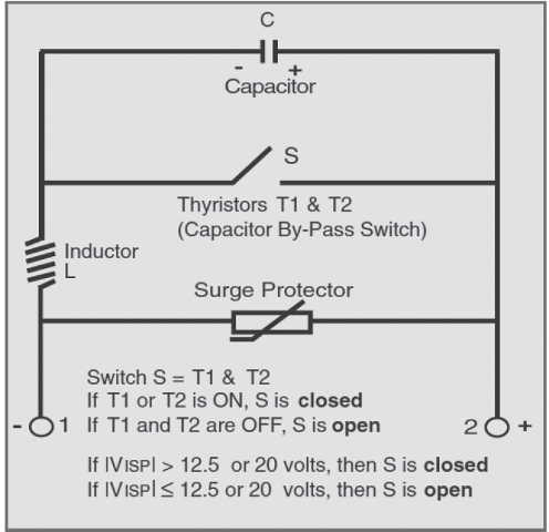
Figure 1: Simplified Circuit of an ISP
Functions of an ISP
Steady-State AC Operation
As seen in Figure 2 below, under normal operating conditions, when AC voltage is applied to the ISP, current flows through the inductor (L) and capacitor (C), supporting continuous conduction up to the selected steady-state AC current rating. The switch (S) and surge protection circuit remain open, and no current flows through them.
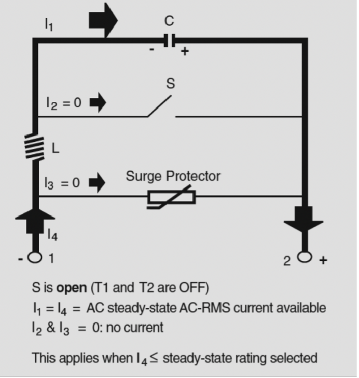
Figure 2: Steady-State AC Current Flow
AC fault current operation
The ISP is designed to withstand currents above its steady-state AC current rating, which means that during AC faults, it is protected against failure, however it no longer blocks DC. Whenever the device operates beyond its steady-state AC current limit or the DC voltage exceeds the switching threshold, a red indicator on the ISP cover flashes intermittently as a warning.
As shown in Figure 3, during an AC fault, the predominant current flow path moves through switch S1 (S) with minimal current flow through the capacitor (C). During this time, the capacitor (C) is protected from excessive current and voltage. There is no current flow through the surge protection path.
Dairyland ISPs are rated for 35kA, 68kA or 118kA, 1 cycle at 60Hz. Some older models remain in operation as well in 7kA and 24kA ratings.
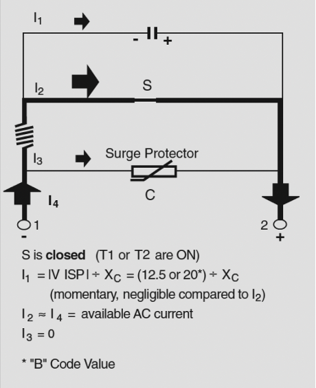
Figure 3: Current Path During AC Faults
Lightning and transient event operation
Under lightning (or switching transient) surge conditions, where the input current has a very fast rise time, the conduction path through the ISP is different than for AC conditions.
Please note Figure 4 below. When the ISP is exposed to a lightning surge, the voltage developed across the inductor (L) instantly rises to a value that places the surge protector (metal oxide varistor) into conduction, enabling the surge protector to carry the bulk of the current. Since the peak voltage across the thyristor also rapidly exceeds the threshold level, switch S is also put into conduction. However, the impedance of the current path through the thyristor is now much higher because the inductor is in series with this path. The impedance of the inductor allows only a small fraction of the surge current through the ISP to be carried by the thyristors, thereby preventing failure of the thyristors due to excessive rate of change of current. Most of the current will travel along the lower impedance path through the surge protector.
ISPs are rated for 75kA (standard) or 100kA (optional) 8x20ms waveform.

Figure 4: Current Path During Lightning Faults
Testing an ISP in-circuit
This test is completed with the device connected in-circuit — no terminal disconnections needed. Please note: this test only checks for internal shorts and not logic control circuit functions.
Refer to and follow company safety procedures prior to testing.
Equipment Required
- A multimeter with AC/DC amperes, volts, ohms.
- A clamp-on AC/DC ammeter
The ISP should be completely silent (noise-free). If an audible clicking sound is heard, the ISP is being subject to an AC current that is above its rating for the DC voltage applied. This sound is caused by a magnetic effect of certain solid-state components and is not any form of electrical arcing. In addition, a red indicator on the cover of the ISP will flash intermittently.
To verify that the ISP is functioning properly, first measure the AC voltage across the terminals using the DMM. Second, measure the AC current flowing through the negative terminal. Finally, calculate the impedance, Vac/Iac. These values should be approximately equal. Refer to the impedance table in this article and the nameplate of the ISP to determine the correct value to compare to.
Example1:
- Vac measured across terminals = 1V
- Iac measured with clamp-on = 10A
- Impedance Calculated = 1V / 10A = 0.1Ω
- For ISP with 90A rating, Published Impedance = 0.09Ω
- Values agree = Unit passes
Example 2:
- Vac measured across terminals = 0.1V
- Iac measured with clamp-on = 10A
- Impedance Calculated = 0.1V / 10A = 0.01 Ω
- For ISP with 90A rating, Published Impedance = 0.09Ω
- Values disagree = Unit fails test
- Unit is actively conducting or failed shorted.
- LED flashing if conducting (if present)
Testing with ISP Tester
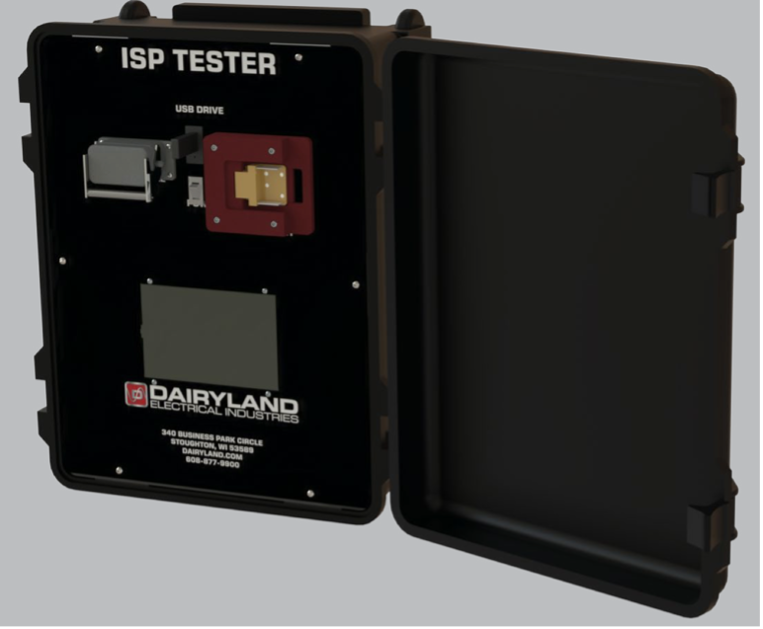
Figure 5: ISP Tester
The ISP Tester is an automated test device for performing in-circuit analysis of an ISP. The ISP is typically connected between the casing of a power utility pipe-type transmission cable system and the substation grounding system. Performing the functions of DC isolation and AC grounding for the transmission casing/sheath, an ISP is not easily removed from the system for the purpose of testing, therefore the ISP Tester performs an important role in analyzing an in-service ISP to determine its health.
The ISP Tester automatically evaluates the ISPs as-found condition and applies simulated AC fault signals to verify proper operation. It confirms that the ISP transitions into the low-impedance (ON) state under fault conditions, then reliably returns to its normal mode, blocking DC (from stray sources or cathodic protection systems) while allowing induced or coupled AC to pass to ground.
The ISP tester is initially configured via a simple touch panel interface. Following configuration, an automated test sequence is initiated by the operator. During the automated portion of the testing, the ISP is subjected to a multi-step test sequence controlled entirely by an on-board microprocessor. The sequence consists of various observational phases followed by two injections of a high current, short duration pulse which creates a temporary “fault” condition. During the test, the ISP is observed to verify that it properly triggers at either the 12.5V or 20V settings as initially selected on the touch panel and that the ISP properly recovers from a triggered condition. The brief high energy pulse causes the ISP to trigger only for a matter of several milliseconds, and a shorting system is applied to the external terminals to limit any influence on the external system. Operators of the ISP Tester should avoid contact with the exposed terminals of the ISP under test. Once initiated, the full test sequence requires approximately three to five minutes to complete. At the conclusion of the automated test sequence, informational data is combined with the actual test results and logged to a USB data drive.
If the ISP tester detects a problem during testing it will report the results in the home screen status box and abort any additional testing. There are fourteen possible failures and three successful results reported to the operator.
The ISP tester is available for purchase or rental. Please contact Dairyland for additional information.
Additional information may be found in the ISP’s technical literature, installation instructions and application guide. If you have any questions on the operation or testing of ISP’s, please contact Dairyland’s Technical Support team for guidance.
ISP Frequently Asked Questions
Frequently Asked Questions about Dairyland’s ISP
Dairyland’s ISP is the original solid-state AC conducting/DC blocking device designed for the corrosion prevention industry and features the most flexible and wide range of product ratings and applications available to the market. The ISP provides the widest range of features and ratings, including the highest levels of AC fault-handling capability – up to the highest typical transmission system faults making it the preferred product for power utility underground cable decoupling/bonding requirements. The following are some of the most frequently asked questions about ratings, logic board functionality, and installation.
To learn about the ISP’s different operating modes and how to test them, please see this article.
What is the leakage current of an ISP?
A relatively small DC leakage current is present during DC blocking, AC continuous operation. Figure 5 below provides an estimate of expected DC leakage current, which is dependent upon the DC voltage available at the terminals. We advise users to expect around 25mA per Volt.
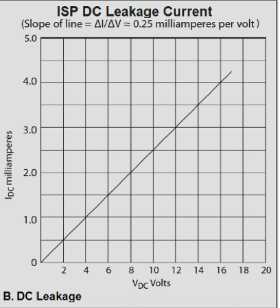
Figure 1: ISP DC Leakage Current
What is the importance of the logic circuit?
The most important component of the ISP is the logic-controlled circuit. This circuit determines exactly when the high current capacity thyristors should be turned “ON”. After a transient event, the circuit ensures the ISP returns to its normal operating mode, blocking DC while conducting AC. This prevents the thyristors from remaining in the ON state due to influence from a cathodic protection system or an external DC voltage source. The logic-controlled circuit, as with the entire ISP, is autonomous and does not require an auxiliary source of electrical power. It captures and stores the necessary power from any event that causes the voltage across, or the current through, the ISP terminals to reach the threshold level. Power is stored for a sufficient amount of time while the logic-controlled circuit deals with any foreseeable event.
The logic-controlled circuit includes a sub-circuit which provides a means for dissipating the stored inductive energy to prevent retriggering of the ISP. After this inductive energy is dissipated, the DC voltage will return to its normal steady-state value. The logic-controlled circuit then automatically goes dormant until the next triggering event occurs. The logic-controlled circuit differentiates between voltage rise caused by stored inductive energy, which should be safely dissipated, and external disturbances such as lightning surges or AC faults, where the ISP must trigger ON to protect itself and to limit voltage between its connected terminals.
Note on Revision 1 logic control circuit
The original logic-controlled circuit, designated as Revision 1, was introduced in the early 1990’s. This circuit revision does not protect an ISP from failure if the steady-state AC current is continually above rating. The Rev. 1 logic circuit does not include the following safety features:
- Prevention of capacitor overheating due to repeated retriggering if the ISP is operating above its steady-state ratings.
- Protection of the capacitor from excessive AC current that can occur below the absolute voltage threshold level of the ISP (applies when the 20V threshold level is selected).
- Provision for activating a flashing red warning indicator whenever the ISP is being repeatedly retriggered (due to application above steady-state rating).
ISPs with the original Rev. 1 logic control circuit were designed over 30 years ago, utilizing the most cutting-edge technology available at the time. Since that time, many technological advancements have been made. Dairyland now recommends that users of the older units consider upgrading to the newest Rev. 5 units.
Note on Revision 5 logic control circuit
Dairyland’s current ISP models utilize the latest Rev. 5 logic control circuit, which feature the following benefits:
- Inductive energy dissipation circuit that assures ISP remains OFF after fault event upgraded by 50% capacity for all models.
- Improved backup triggering of 26Vpeak if primary triggering fails.
- Prevention of capacitor overheating due to repeated retriggering if the ISP is operated above its steady-state ratings.
- Protection of the capacitor from excessive AC current that can occur below the absolute voltage threshold level of the ISP.
- 20V blocking voltage threshold standard.
- 90Arms steady-state AC current rating standard for models up to 68kA.
- 120Arms steady-state AC current rating for 118kA model.
What is the difference between 40 and 100 rating of logic control circuit?
These ratings indicate the maximum allowable DC current that can flow through the ISP during its conducting mode while still enabling the device to be automatically reset back to its normal mode after a fault condition. 40 is the standard rating, and it is capable of 40Adc. The 100 rating is optional, with capability of 100Adc.
Note that ISPs with Rev. 5 logic control circuit have 50% more capacity due to circuit improvements.
What is the impedance of an ISP?
For ISP units manufactured prior to 2020, the impedance value will vary depending on the steady-state current rating, as there were four options available. Impedance values are shown below:
| Steady-State ACrms Rating | mW (60Hz) | mW (50Hz) |
| 30A | 265 | 318 |
| 60A | 133 | 160 |
| 90A | 90 | 110 |
| 120A | 70 | 80 |
Table 1: Impedance values based on steady state current rating of an ISP
For ISP units manufactured in 2020 or later, only the 90A and 120A steady-state current ratings are available. The 90A and 120A impedance values shown above apply.
What is the difference in model numbers prior to 2020 and post-2020?
The ISP model number was streamlined in early 2020 for easier specification. Prior to 2020, there were numerous options that led to many variations of ISPs. The changes affected the steady-state current ratings, tamper-proof screws, and blocking voltage threshold.
The steady-state current ratings went from four options (30-120Arms) to only two options (90Arms or 120Arms), the blocking voltage threshold changed from two options (12.5V or 20V) to just the 20V option and finally, tamper-proof screws on the enclosure cover were made standard on all ISPs.
What is the purpose of the LED light?
The red LED indicator will flash approximately once per second if the DC voltage is above the voltage blocking level (12.5V or 20V), or if the steady state AC current is above the steady state rating of the ISP model (30A, 60A, 90A or 120A). Under normal operating conditions this LED should always be off.
If either of the above conditions occur, there will be an audible “clicking” sound as the thyristors are being switched.
Can ISPs be connected in parallel?
Single ISP models 35kA and 68kA should not be connected in parallel to double the AC fault current rating capability. The primary concern is that the logic control circuits are not synchronized to trigger at the same time during fault events. One of the units will trigger while the other one will not, thus the unit that triggers will see the full fault event and likely causing the ISP to fail.
For applications that require higher AC fault current capabilities, Dairyland recommends our highest rated ISP, the 118kA. This unit essentially has two single 68kA ISPs connected in parallel at the terminals and the logic controls circuits are synchronized together eliminating the issue mentioned above.
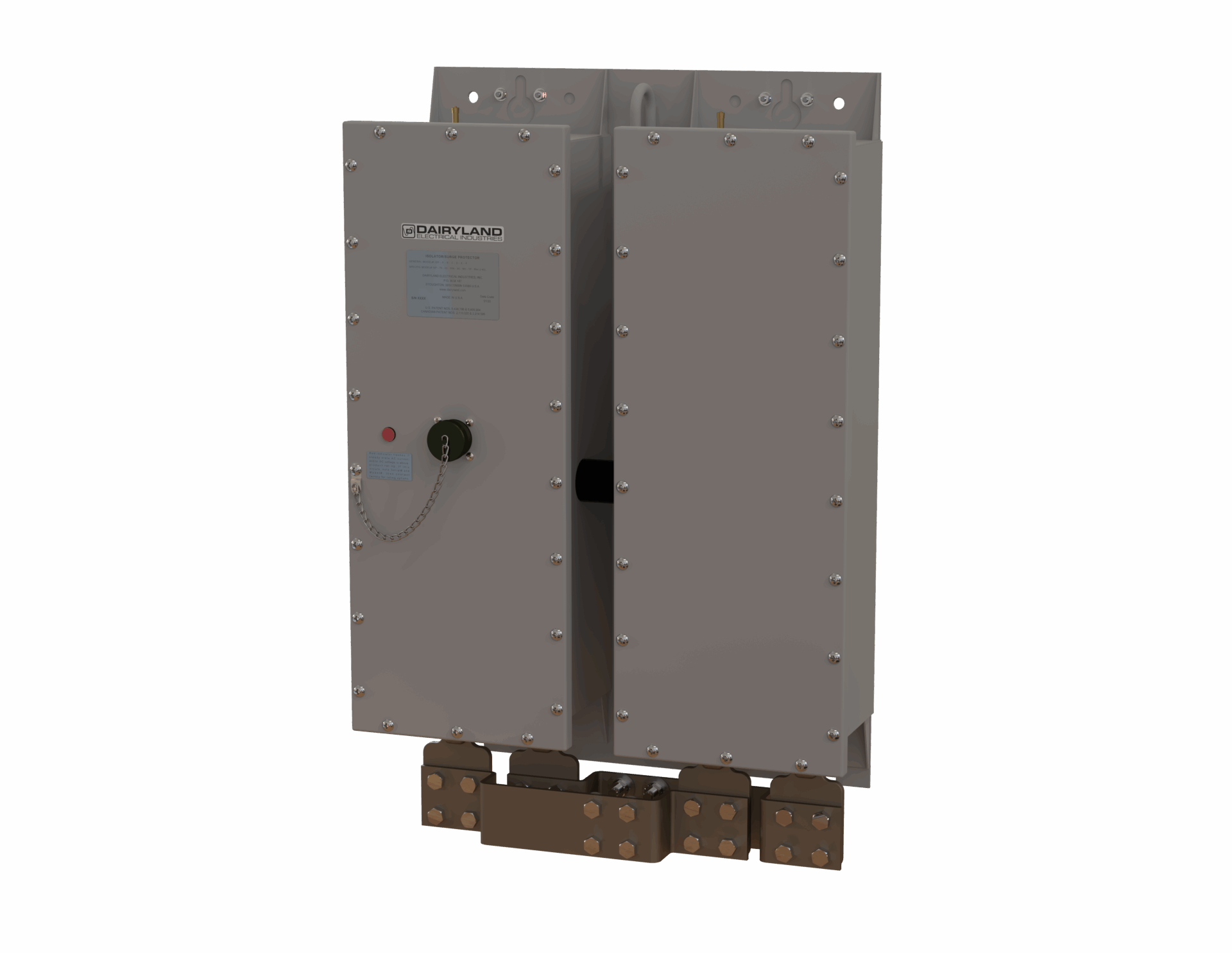
Dairyland’s ISP 118kA is recommended for applications that require higher AC fault current capabilities
Is an ISP listed for hazardous location use?
The ISP is a sealed, non-spark-producing device. This device meets the intent of ANSI/NFPA 70 (the U.S. National Electric Code) and CSA (Canadian Standards Association) requirements for Class I, Division 2 hazardous locations. The ISP has not been submitted for listing for hazardous locations because it is seldomly used in hazardous locations. If a listed device is required for hazardous locations, consider the PCR or PCRH, described in other literature sections.
Read more here about ISP’s different operating modes and how to test them.
If you have any questions regarding the information in this article, please feel free to contact us at techsupport@dairyland.com.
INTRODUCTION
Within facilities such as pipeline stations and tank farms, cathodic protection (CP) is most easily achieved when the protected structure is electrically isolated from other structures and grounding systems. This allows for lower current requirements from CP current sources, such as rectifiers or galvanic anodes, and generally allows the operator to achieve the required voltage criteria for protection against corrosion.
However, electrical equipment connected to the structure, such as motor operated valves and instrumentation, must be electrically grounded to provide protection against AC faults and lightning or to provide a suitable ground reference for instrumentation. If such equipment and the associated grounding systems are properly isolated from the cathodically protected structure through the use of isolation joints and/or dielectric fittings, there is no impact on the CP system.
However, it is not uncommon for many cathodically-protected structures to be inadvertently bonded to other structures and grounding systems and this results in the CP system having to protect not only the coating defects on the intended structure, but also the other structures and grounding systems to which it is bonded.
In addition to the local facility grounding system, the power utility grounding system to which the facility is bonded presents a large and unknown amount of buried metallic surface area in the form of copper ground rods and other grounding electrodes, as illustrated in Figure 1. Moreover, the facility is also bonded to all the other utility customers’ grounding systems. This vast bare surface area becomes part of the cathodically protected structure from a current-requirement perspective, overwhelming the CP design goals, and allowing unintended interaction to occur. High rectifier output to meet the current demand can also cause excessive voltage gradients in the soil that result in interference with other nearby structures, including both owned and foreign systems, affecting CP potentials, and possibly causing corrosion.
These negative effects can be prevented by judicious application of DC decouplers. Solid-state decouplers provide effective DC isolation while maintaining a safe grounding path for AC faults and lightning. Decouplers are bi-directional, two-terminal devices that feature power semiconductor-based isolation and switching. Fail-safe designs ensure that any exposure to conditions that exceed the device ratings result in an uneventful fail-shorted condition, hence the term “fail-safe”. Under normal operating conditions, the device blocks DC and conducts AC up to a predetermined voltage threshold of typically several volts. During an over-voltage event, upon reaching the voltage threshold, the decoupler instantly switches to the fully conducting mode, clamping voltages (AC and DC) to low and safe levels. After the event, the voltage drops below the threshold and the decoupler automatically switches back to the DC blocking/AC conducting mode.
Two accepted installation methods exist for applying decouplers to isolate CP protected facilities from grounding systems, each with its relative advantages: Installation in the grounding conductors of individual electrical devices and installation at the transformer feeding power to the facility.
The most advanced decoupler in the world, the PCRX, is virtually invisible to interrupted survey testing and provides simultaneous DC decoupling and AC continuity/grounding when used with cathodically protected structures.
AC mitigation, where decouplers are installed between the pipeline and the mitigation grounding system, is the most common application for the PCRX. In most AC mitigation applications, there is significant AC interference with the pipeline resulting in several amps of induced current to flow through each decoupler to the grounding system. However, in some applications with relatively low AC interference, less than 1 Arms may flow through individual decouplers. In these rare cases, the PCRX may operate differently, and it is important to understand how this could affect your pipeline.
PCRX Operation with Low AC Current
The PCRX operates differently on pipelines having lower AC interference, specifically when the AC current flowing through the PCRX is below 0.6 Arms. The AC impedance of the PCRX varies with AC current, and below 0.6 Arms, the impedance is significantly higher than that at higher AC current levels, as shown in the chart below.
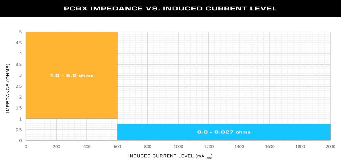
Figure 1
How Could This Affect My Pipeline?
In most cases, the higher impedance at low induced AC currents has little effect on the operation of the PCRX or the pipeline. Even at its highest impedance levels, the PCRX will maintain a maximum of 2 Vrms AC across the terminals under normal operating conditions, therefore keeping the pipeline AC potentials low near the PCRX pipeline connection. But other possible effects of the higher impedance at low current levels should be considered.
Influence on Blocking Threshold Selection
Since decouplers go into full conduction when the total voltage across the terminals reaches the threshold voltage, both DC and AC voltage across the terminals during normal operating conditions must be considered when choosing threshold voltage ratings. For example, assuming the maximum of 2 Vrms (2.8 Vpeak) AC across the PCRX terminals, the -4.5/+3.5 V threshold rating would permit a maximum DC operating voltage range of -1.7 V to +0.7 V. Similarly, in this case, the -5.5/+2.5 V rating would allow for a maximum DC operating range of -2.7 to -0.3 V. The PCRX threshold voltage ratings were designed to accommodate most DC operating conditions even under maximum steady state AC levels.
Possible Effect on AC Current Density
AC mitigation systems are designed to create a low resistance path to ground for induced AC. The impedance of any device in this path can affect the AC current density readings on the pipeline. This is why Dairyland decouplers, including the PCRX, are designed to have low nominal AC impedance. However, in rare cases when the PCRX impedance increases due to low induced AC levels, increased measured AC current density may be observed along the pipeline. The actual impact depends on the specific system design, soil resistivity and other system factors. The impedance values published in the PCRX Technical Literature should be incorporated into AC mitigation models when evaluating design goals for voltage and current density.
Potential Impact on AC Rail Interference Applications
It can take up to 15 seconds for the PCRX to transition from high to low impedance. For AC rail interference and other applications where there may be rapid transitions in AC interference from below 0.6 Arms to higher current levels, the PCRX may remain in a high impedance mode for several seconds even though the AC current has increased above 0.6 Arms. During this short transition period, the resulting elevated AC voltage across the terminals may cause the PCRX to go into conduction and a momentary loss in DC isolation. The PCRX would still provide AC mitigation and over-voltage protection. However, be aware that measured pipeline potentials may be affected during this brief transition period and should be discarded.
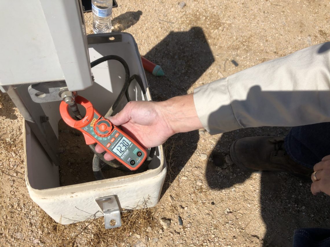
Figure 2
How can I know if my PCRX will have low AC current?
AC mitigation system modeling is recommended as a best practice for new installations. Modeling not only predicts an optimal design for control of AC interference, but also allows for estimating AC current flow through mitigation systems during steady-state and fault conditions. This information can be used to select proper decoupler models and determine at what impedance PCRX units will operate. PCRX impedance values found in the PCRX Technical Literature should be incorporated into AC mitigation models when evaluating systems with PCRX units.
For existing installations, the steady-state AC current can easily be measured using a clamp-on ammeter as shown in Figure 2.
Contact Dairyland for recommendations on PCRX application if steady-state AC current is either modeled or measured to be less than 0.6 Arms.
PCRX Will Always Improve Interrupted Survey Data
Even at low steady-state AC current levels, the PCRX will always improve the accuracy of instant-off measurements without having to disconnect the PCRX from the pipeline. And it will always provide DC isolation from grounding systems while simultaneously protecting the pipeline from over-voltage conditions such as AC faults and lightning.
Cathodic Protection (CP), when properly applied, is an effective technique to minimize the natural corrosion process that occurs on pipelines, tanks and other buried steel structures. To maintain effective CP coverage with minimal current demand, the structure must be well-isolated from earth for DC current flow. This is commonly accomplished using high resistance coatings, isolation joints, dielectric fittings and isolation pads.
However, these structures require electrical earthing for both personnel safety and protection of the structure from damage due to over-voltage conditions. Earthing bonds for AC mitigation systems, AC fault and lightning protection and electrical equipment protection all introduce undesired paths for CP current to return to the rectifier by way of the structure. This requires the CP system to protect significantly more material surface area for which it was not designed. As a result, it is often difficult to maintain adequate CP potentials on the structure that is to be protected.
DC decouplers have a long history of providing effective DC isolation of cathodically protected structures from other objects and earthing systems while simultaneously bonding the structure to earth for AC and lightning. However, decoupling devices are often misapplied or not applied at all due to simple misunderstanding of how CP current flows through earthing systems.
THE CHALLENGES WITH EARTHING SYSTEMS
CP systems, and external corrosion protection in general, require that the structure be electrically well-isolated from earth. Since CP systems are designed to protect only relatively small defects in the coating of the protected structure, the degree of isolation determines the efficiency and effectiveness of the CP system in protecting the structure. Certainly, the less surface area of the structure that is directly in contact with earth, the less CP current is required for protection. This is the basic function of high resistance pipeline coatings. Additionally, every surface on the structure that interfaces other earthed structures must be insulated to minimize CP current flow through the other structures. This is accomplished using isolation kits and monolithic joints at piping connections, dielectric fittings for smaller piping connections, conduit and sensor connections and isolation pads for above-ground pipe supports.
In addition to these mechanical interfaces, there are electrical connections between structure and earth for which continuity must be maintained to protect the structure and personnel from potential over-voltage conditions. These connections include earthing bonds for AC mitigation systems and protection from AC faults and lightning and earthing bonds for electrical equipment.
AC Mitigation Earthing Paths
The main intent of AC mitigation systems is to dissipate unwanted voltage along the pipeline resulting from induced AC from nearby power transmission lines and AC faults and lightning. The general technique for mitigating induced AC pipeline voltage is to connect the pipeline at appropriate locations to a suitably low impedance earthing system in order to collapse the voltage to a safe value. The earthing system is commonly bare zinc ribbon or copper wire run in parallel with the pipeline.
The design process typically begins with software modeling by specialized consultants, inputting various factors such as soil resistivity, separation distance and voltage to arrive at a voltage map at all points along the pipeline. Then, by applying low impedance earthing points at various locations along the affected area, the AC effects under steady-state and fault conditions can be modeled, and the earthing system design can be optimized to address worker safety and AC corrosion issues. Depending on many variables such as the separation distance and geometry between the pipeline and power lines, power levels, soil resistivity, pipeline coating, etc., spacing of earthing connections may vary between a few hundred meters to several kilometers.
These bonds between the pipeline and the earthing system provide additional low impedance paths for CP current to flow between the anode bed and the rectifier negative terminal and so introduce significant additional material surface area for the CP system to protect as illustrated in Figure 1. As a result, the rectifier often cannot support the increased current load and CP potentials can become compromised, leaving the structure inadequately protected.
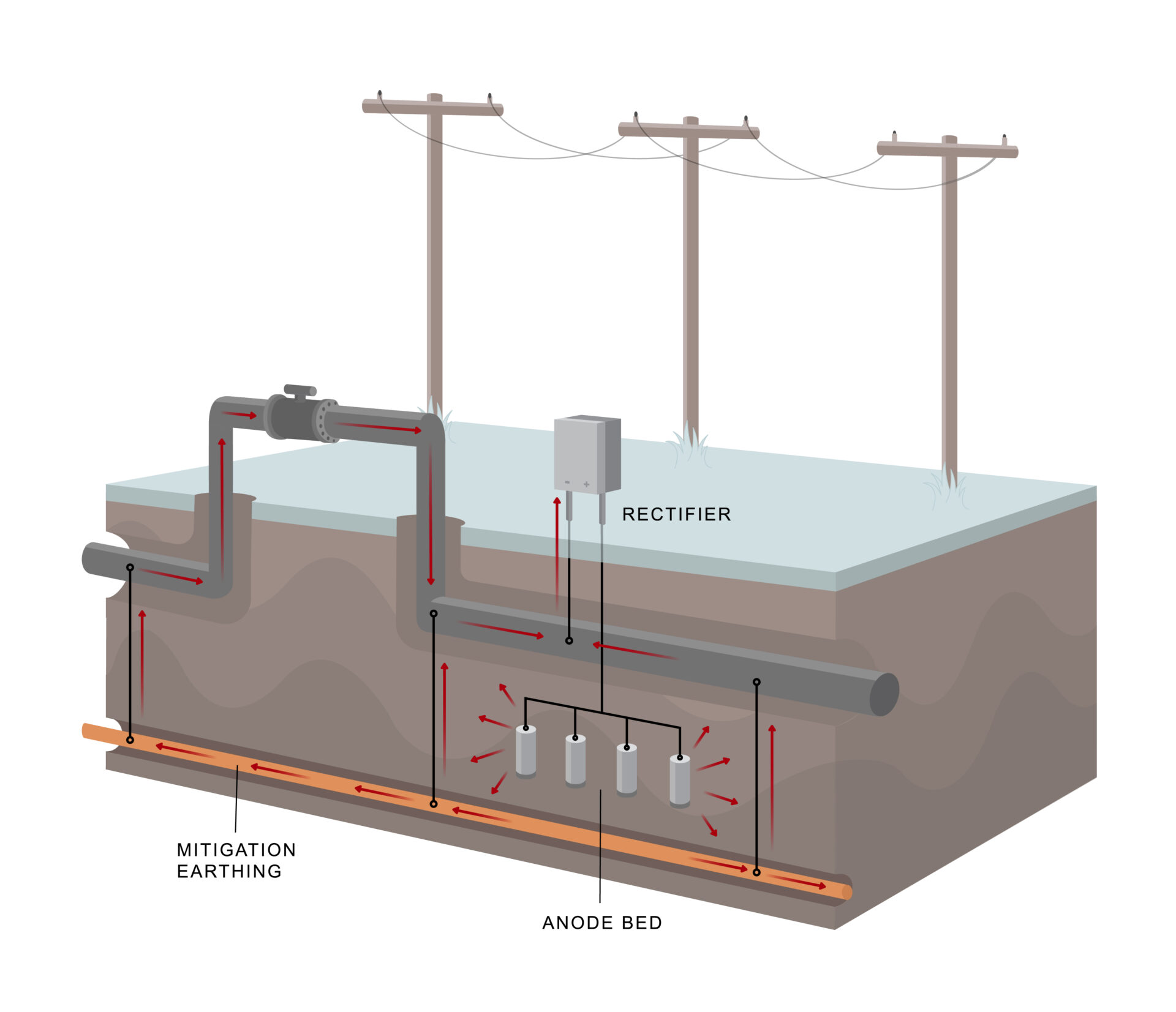
Figure 1: CP Protection of AC Mitigation Systems without DC Isolation
Electrical Equipment Earthing
It is common for electrical equipment, such as motor operated valves, to be inadvertently electrically bonded to pipelines. Consequently, the equipment, its earthing system and everything to which it is bonded, including the utility earthing system, is bonded to the pipeline. These earthing systems then become additional paths for CP current to return to the rectifier negative terminal and so present additional material to be protected by the CP system as shown in Figure 2. This can have a dramatic negative impact on CP system performance.
Electrical earthing conductors are needed to conduct AC fault current and prevent over-voltage conditions and must be left in place. National electrical codes require equipment earthing conductors to be 1) permanent and continuous, 2) rated to handle the anticipated AC fault current from the source, and 3) of low impedance to allow AC fault current to flow, permitting a clearing device (circuit breaker or fuse) to clear the fault. These define what is an “effective ground-fault current path” for safety, per the electrical codes[1]. To remove the offending conductor for convenience on the CP system is to allow an unacceptable shock hazard at the site during any over-voltage condition.

Figure 2: CP Protection of Electrical Equipment Earthing without DC Isolation
Instrumentation Earthing and Measurement Tubing
Transmitters on pipelines and tanks typically have a continuous metallic shield that covers the signal cables and may have an additional internal earthing conductor as well, as shown in Figure 3. Except in the case of a transmitter that has an electrically isolated body, the shield and earthing conductor will short the structure to the instrument earth and cause CP current to protect the instrument earthing system.
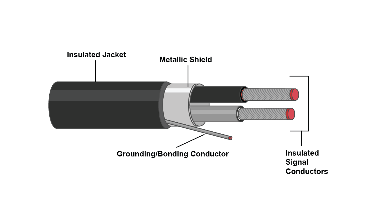
Figure 3. Typical Signal Cable
Similarly, pipeline pressure measurement or equipment control tubing often bridges between cathodically protected and unprotected structures and can introduce a path to earth for CP current.
DC ISOLATION TECHNIQUES
When faced with insufficient CP potentials due to such required earthing bonds, CP designers might be inclined to add more rectifiers and anode beds and tolerate high CP current demand. However, this is likely a prohibitively expensive option and may ultimately not provide sufficient protection.
A practical and widely accepted solution is to install DC decoupling devices in series with the bonding connections between the cathodically-protected structure and the earthing systems as shown in Figure 4. When used in series with electrical equipment earthing systems, note that the device must be specifically approved for such use and that use of DC decouplers in earthing systems must comply with local national guidelines and codes. This prevents CP current from passing through the earthing systems and so minimizes the amount of CP current required to protect the pipeline.
Solid-State Decouplers
Solid-state over-voltage protectors use high power solid-state electronic switching components to create a switch between the two structures to be isolated. Under normal conditions, this switch remains open, maintaining DC isolation between the structures. When the differential voltage across the terminals exceeds a prescribed voltage threshold, which would occur during a fault or lightning event, the switch closes virtually instantaneously, collapsing the voltage across the terminals and electrically bonding the structures. Immediately following the over-voltage event, the device then automatically switches back into the OFF state to maintain DC isolation.
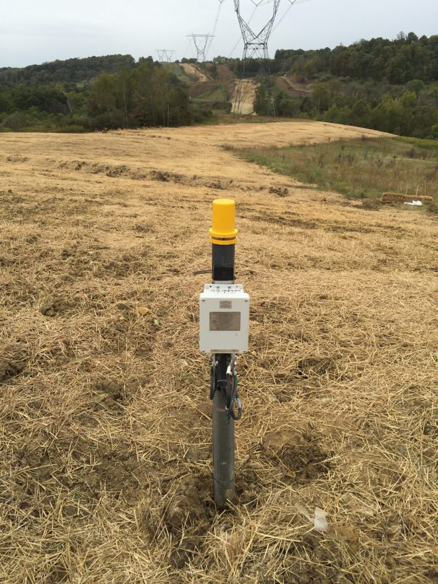
Solid-state decouplers, in addition to bonding structures during AC faults and lightning, provide a continuous conduction path for steady state AC to pass through the device at all times. By shorting steady state induced AC current, a solid-state decoupler reduces AC voltage on the pipeline and prevents the AC voltage from triggering the solid-state switch. An example of a solid state decoupler installed as part of an AC mitigation system is shown in Figure 5. In Figure 6, a decoupler is shown installed to DC isolate a motor-operated valve from electrical earthing.

Figure 4: CP Protection with DC Isolation using Decouplers
 |
 |
|
Figure 5. Solid-state decoupler installed as a part of an AC mitigation system. |
Figure 6. A decoupler installed to DC isolate an MOV from earth. |
Polarization Cells
The polarization cell is an electrochemical switch comprised of pairs of stainless steel or nickel plates immersed in a solution of potassium hydroxide. It responds to low voltage DC current by polarizing the plates and reducing the flow of DC current. It passes higher voltage DC, steady state AC, AC faults and lightning current.
Since the introduction of solid-state devices in the 1980’s, polarization cells have become much less common due to their need for regular maintenance of fluid levels, large package size, and the fact that when they fail, they create an open circuit, which creates a potential safety hazard.
Other DC Isolation Devices
Though not considered decouplers, spark gap devices are commonly used to protect isolation joints from damage due to lightning. When the voltage across the terminals reaches a designated level, an arc bridges the product’s two electrodes and passes current. Typically, spark gaps require several hundred volts for AC and over 1000 V for lightning for the device to go into conduction. Although they do provide DC isolation, they cannot pass low voltage AC current and so are not appropriate for use with AC mitigation systems. In addition, spark gaps do not provide an effective ground fault protective path as defined by electrical codes and so cannot be used in the earthing circuit for electrical equipment.
APPLICATION REQUIREMENTS FOR DC DECOUPLERS
Decoupling products must be selected with careful examination of their electrical characteristics relative to the intended purpose in order to assure proper application.
Low Impedance for AC Faults and Lightning
One of the most basic requirements of decoupling devices is to provide a low impedance path for AC faults and lightning. During such an event, the voltage across a solid-state device clamps at the threshold voltage, which is typically 3 volts or less. Under the most extreme AC fault conditions, the maximum voltage across the terminals is less than 10V. Under lightning surge events, this maximum voltage is approximately 100V. This assures that over-voltages will be clamped to low levels during faults or lightning events, providing a significant advantage for personnel safety and for applications such as isolated joint protection.
Sufficient Device Ratings
The typical AC fault rating for pipeline applications near HVAC towers is 5kA and levels up to 15kA are not uncommon. Most solid-state devices have the ability and ratings to handle AC fault current at these levels.
Low Impedance for Steady State AC
To be effective for use as part of AC mitigation systems, decoupling devices must be able to continuously conduct steady state induced AC. This includes devices used across isolation joints if earthing points on the opposite sides of the joint are part of the same AC mitigation system. Solid-State decouplers and polarization cells both continuously conduct steady state AC. Most solid-state decouplers introduce only a few milliohms of impedance and so do not significantly affect the pipeline voltage.
Low Maintenance
Given the remote location of many pipelines, low maintenance and reliability of decoupling devices is extremely important. Since polarization cells require regular inspection to maintain liquid levels, these devices have become much less popular over recent decades.
Low DC Leakage Current
To maintain the efficiency of CP systems, it is important to minimize DC current leakage to earth through decoupling devices. Since many modern pipeline coatings provide such effective isolation, CP rectifier currents are often so low that several milliamps of DC current loss to earth through a decoupling device can negatively affect CP performance. Solid-state decouplers, when properly applied within the threshold voltage range, typically have less than 10mA DC leakage.
Hazardous Location Ratings
Many user sites are formally classified as hazardous locations, which are defined by international standards such as the International Electrotechnical Commission (IEC) according to the concentration of flammable gases or liquids present. Electrical devices must meet certain design and quality requirements to be used in these locations. If a site is classified or otherwise treated as a hazardous location, then an over voltage protection product having third-party certifications (UL, ATEX, IECEx) for this environment should be used.
Fail-Safe Design
If exposed to fault current values beyond their ratings, over voltage protection devices should always fail safely and un-eventfully in the shorted mode (fail as a dead-short), bonding the two points together for safety. This assures that over-voltage conditions will be addressed – whether the product is working or failed.
Most solid-state devices are considered truly “fail-safe” and product certifications should provide verification as such. When polarization cells fail, either from fluid evaporation or tank rupture, they fail as an open circuit and cease to provide safety earthing.
CONCLUSIONS
To minimize corrosion, pipelines and storage tanks rely on expensive coatings, isolation joints and cathodic protection system to electrochemically isolate the structure from the earth. However, to mitigate the damaging and hazardous effects from AC interference and lightning, these structures require intentional earthing systems. These conflicting requirements have been addressed, in general, by the widespread use of DC decouplers. Decouplers, when installed in electrical connections between CP-protected pipelines and earth, provide both DC isolation and bonding for AC and lightning.
However, not all DC decoupling devices are created equal. For example, spark gap devices should not be used for most applications located near HVAC power lines since they do not pass low voltage steady state induced AC to earth and they are not properly rated to handle AC faults levels that are typically observed on pipelines in these locations. In addition, many DC decouplers have not been well validated by reputable third-party certification agencies to meet stated performance criteria. It is important to thoroughly understand the performance strengths and limitations of the devices before application.
REFERENCES
1. US National Electrical Code, NFPA 70, Article 250.4(A)(5).
All Dairyland decouplers block DC and simultaneously ground AC during normal conditions, and provide over-voltage protection during AC fault and lightning conditions. This combination of isolation and grounding makes Dairyland solid-state decouplers ideal for a wide variety of applications where isolation is beneficial for CP system performance, but safety grounding is critical for safety.
For a hands on demonstration of how decouplers respond to various field conditions, use the link to the right to access our decoupler simulator. If you have questions about the simulator or would like to learn more about Dairyland, please contact us.
Prepared for and presented at the 2015 NACE Central Area Conference, this presentation discusses the use of decoupling devices to provide safety and CP isolation on a variety of facilities and equipment. This session covers the types of structures found in facilities, what types of grounding/bonding problems you might face, hazardous locations and how to fix these issues and concerns.
Cathodic protection systems and power utility networks are located in the same geographical areas, and sometimes these systems interact in unintended ways. This case study shows how a power utility system acted as a conduit for CP current and caused corrosion at a surprising location.