
Airport fueling stations depend on piping, storage tanks and electrical equipment to deliver jet fuel. To protect these assets, cathodic protection (CP) systems are used to prevent corrosion on buried portions of the piping and tank bottoms. In addition, to maximize CP system efficiency, these stations are isolated through high resistance coatings and electrical isolation joints at pipe flanges and connections to electrical equipment.
These fault and lightning events can apply high voltages to the isolation fitting, which can cause the isolation material to fail. When this occurs, the steel flange face can be damaged due to arcing and heating from excessive current flow. This arcing and isolation material failure can lead to product ignition if there is a product release associated with the over-voltage event. Protection against over-voltage conditions is needed on fueling stations to assure continued operations while also minimizing personnel risk.
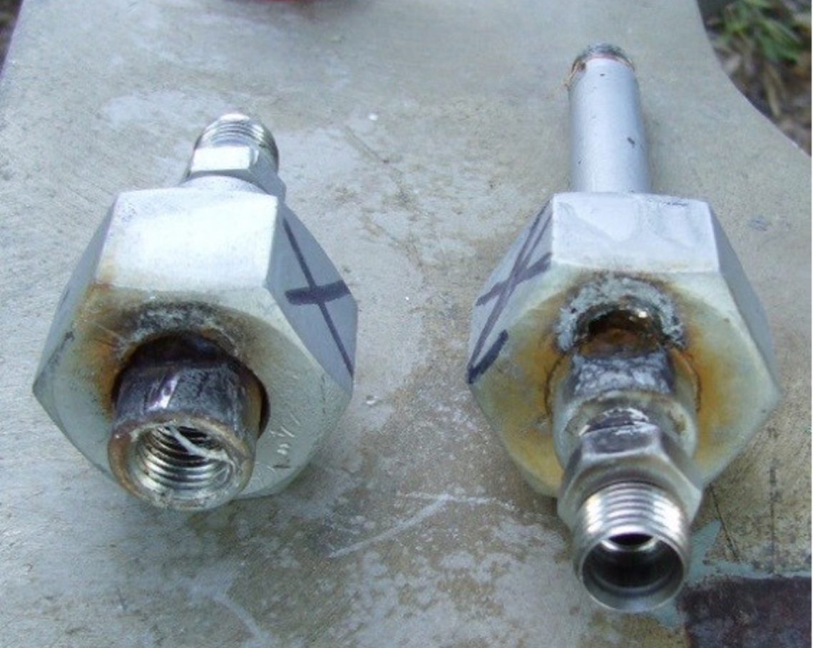
Failure of dielectric union due to over-voltage fault.
Dairyland Solid-State Over-Voltage Protectors
Connecting a Dairyland solid-state over-voltage protector (OVP) device across an isolation joint will protect against AC faults and lightning events by providing a current path around the joint and limiting the voltage to safe levels to protect the isolation system and personnel working in the area. During a fault, these devices instantly switch into their protective mode, and then automatically switch back to an open or OFF mode, providing isolation again.
Isolation Joint Codes & Regulations
When addressing over-voltage safety concerns, applied products must address certain safety and compliance standards for the location in which they will be installed.
United States, Including Military Use
Most airport fuel piping applications that involve isolation joints are classified as hazardous locations. These classifications are:
- Class 1 Division 2: Explosive gases or vapors are not normally present
- Class 1 Division 1: Explosive gases or vapors may normally be present
Protective devices must be selected to meet or exceed the hazardous location classification of the airport fueling site. Dairyland offers certified products for either Division 1 or Division 2 classifications.
US Military airport facilities are constructed to the requirements of the Department of Defense UFGS standard 33 52 43.13 for aviation fuel piping, and section 2.1.5.4 for isolation gasket kits and surge protector devices. Dairyland’s OVP and OVP2 were designed to meet these requirements and have been used extensively around the world on US military bases, or other locations where DOD specifications are applied.
International
Many countries recognize and use products certified to the Class/Division system and locations with US military presence, often apply the DOD specification mentioned above.
Other international standards and systems that apply to isolation joint protection are as follows:
- ATEX- for European (EU) applications
- IECEx – for extensive world-wide use
- EAC- for EurAsian Conformity, countries in the EuraAsian Economic Union
Product Recommendations
For aviation isolation joint protection, the following models are recommended:
- For Division 1 (Zone 1):
- Model OVP-2/2-3.7-100 or
- Model OVP-2/2-3.7-100-M8 or
- Model OVP-2/2-3.7-100-M10
- For Division 2 (Zone 2):
- Model OVP2-2/2-3.7-100
- Note:
- The OVP Model encompasses all OVP2 ratings, thus the user could standardize on the OVP to address all installations.
Why Not Use an Arrester?
Lightning arresters and spark gap arresters are often used as lightning protection devices on isolation joints. However, these devices fall short of an efficient, reliable, and safe solution when compared to solid-state over-voltage protection devices and are not recommended for fueling system protection. Some of the short comings include the lack of fail-safe construction, limited AC fault current ratings, low voltage thresholds and their limited lifespan.
For more details, reference technical article Dairyland OVP Devices vs. Competing Technologies.
For more details on using over-voltage protectors on airport fueling station applications download the application guide Airport Fueling Systems Isolation/Bonding.
In this video, presented in top 10 format, we’ll take a look at the top 10 misunderstandings about over-voltage protection that we encounter in the corrosion industry.
Dairyland products are commonly used in cathodically protected systems to provide over-voltage protection due to lightning. Dairyland decouplers and over-voltage protectors are excellent choices for this application, and they carry third party certifications for high levels of lightning current, ensuring their capabilities. However, an often-overlooked factor during installation of over-voltage protection products is the impact of conductor lengths used to connect the device to the protected structure. Paying close attention to the installation method can have a direct impact on the end result of providing adequate lightning protection.
Evaluating Conductor Inductance
Due to the inherent inductance of a conductor, when lightning flows through it, a large voltage may develop between the connection points: The longer the conductor, the greater the inductance and the greater the voltage developed across the conductor. If this voltage exceeds the insulation or coating strength, arcing will occur. As a result, when any product is used to provide over-voltage protection from lightning (e.g. such as across an isolation joint) it is extremely important to recognize the detrimental effect of long conductors used to connect the protective device. To achieve maximum performance, it is critical to keep the conductors as short as possible. Consider the following formula:
V (total) = V (device) + V (conductors)
The conductor length is the total length of the two conductors required. The total voltage developed between the two connection points of any device due to a lightning surge is the sum of: (1) the clamping voltage of the device selected and (2) the voltage developed by the conductors themselves.
Of course, to achieve successful protection, the total voltage across the isolation joint must be below its insulation withstand value. Normal procedure would be to select a protective device with the lowest allowable clamping voltage for the application. Dairyland solid-state devices have a threshold voltage of typically several volts, while spark gap arresters fire at hundreds to low thousands of volts. However, any device also has a total voltage that appears across its terminals during the flow of lightning current, due to the same inductive effect described in this article – a value that is above its threshold voltage.
Example
As an example, assume that the device selected has a clamping voltage of 500 volts at the highest value of lightning surge current anticipated. Referencing the above formula, this results in:
V (Device) = 100 volts
Next, the effect of conductor length will be considered. Any conductor, subject to a current with a very high rate change, will develop an inductive voltage drop along its length. This voltage drop is a function of the conductor inductance (L), and the rate of rise of the lightning surge current (di/dt) as shown in the following formula where L is in microhenries (µH), and (di/dt) is in amperes per microsecond (A/µsec):
V (Conductor) = (L) • (di/dt)
Based on measurements of the conductor sizes normally used to connect Dairyland products, a reasonable estimate for conductor inductance is 0.2 µH per foot of conductor length. (Other sources have suggested a value as high as 0.4 µH/ft.) More recent field measurements of lightning surge currents (direct strokes) indicate that the rate-of-rise (i.e., di/dt) in half of the measurements was 13,000 amperes per microsecond, with the maximum value measured at 60,000 amperes per microsecond.
Next, some sample calculations will be shown using the above data and the following assumptions: L = 0.2 µH/ft, di/dt = 13,000 A/µsec
V (conductors) = 0.2 x 13,000
Result: 2600 volts per ft. of total conductor length
The total voltage that would appear between the two connection points of a surge protective device given the above,realistic, parameters is:
V = V (Device) + V (Conductors)
= 100 + 2600 = 2700 volts if total conductor length = 1 ft.
= 100 + 5200 = 5300 volts if total conductor length = 2 ft.
= 100 + 7800 = 7900 volts if total conductor length = 3 ft.
Note that conductors for each terminal of the device must be one-half of the length shown, assuming equal conductor lengths.
Based on this data, it is easy to recognize the predominant factor that determines the maximum voltage that will appear across the isolation joint (and often, other protected components) is determined by conductor length, not the protective product threshold voltage.
Keep the Conductors Short!
A suggested guideline for conductor length, due to these factors, is a total of 12″ (300mm) including both conductors. This may not be possible in some cases, but the length should still be kept as short as possible.
The actual test data shown below was measured across a Dairyland device during a simulated 50,000A lightning current event. Note that for even short conductor lengths, the voltage across the connection points is significant.

Most typical field installations use much more conductor length than 12″ and may use a protective device such as a spark gap arrester, which has a much higher conduction voltage. This combination effect increases the voltage across the isolation joint (or other structure) to a level that may cause arcing and insulation breakdown.
Choose the Right Mounting Accessories!
 To aid in minimizing over-voltage due to lightning, Dairyland provides numerous mounting accessories designed to minimize the effects of conductor inductance, which can be found in the accessories section of our website.
Where conventional insulated copper conductors are used, keep the conductors as short as possible, preferably less than 12” total, and as close together as possible to minimize conductor inductance.
If you should have questions about this or other products that Dairyland manufactures, please feel free to contact our technical support team.
Providing over-voltage protection to large structures such as pipelines, tank farms and airport fueling systems is a multi-faceted challenge. It requires a solution that not only enhances cathodic protection but also protection against AC faults and AC induction.
As a result, at Dairyland, we hear many misunderstandings about over-voltage protection from industry professionals. To help fix this problem, we’ve created resources to overcome them and to communicate the correct knowledge and understanding to the industries we serve.
The latest resource we’ve created is this helpful infographic, which briefly summarizes the top 10 biggest misconceptions about over-voltage protection.

In this video originally presented at the NACE Central Area Conference, we’ll take a look at insulated joint protection when structures are located in hazardous locations. We’ll discuss the relevant regulations and considerations when applying safety products.
Following up our Top Ten Misunderstandings video, this video includes more commonly heard misunderstandings related to Over-Voltage protection encountered in the corrosion industry.