
We recognize that your time is valuable—and there are lots of decisions to be made pertaining to your next project. When deciding where to buy decouplers and over-voltage protectors, it is important to consider more than the price listed on a sales sheet.
Our goal at Dairyland is to make a safer world by solving complex problems through innovative product design. From our beginnings solving stray voltage issues on dairy farms, to our global impact in the pipeline and high-power industries, we have over four decades of experience building rugged, reliable products that last.
We’ve created the following resource to aid you next time you need a decoupler or over-voltage protector for your project.
 |
How can I know if the decoupler I purchase will perform as specified?
We work tirelessly to deliver our customers the safest, most reliable products on the market. Integrity, safety, and reliability are part of everything we do at Dairyland—it’s in our DNA. We have full confidence that a properly specified product will perform as intended for years to come, because each one of them is thoroughly tested to confirm that they work as intended. But you don’t have to simply take our word for it—you can rely on our third-party certifications to independently confirm that our products do what we say they do.
Learn more about the importance of Third Party Certifications.
Do Dairyland products ever fail? What happens if they do?
Dairyland’s product failure rate is calculated at 0.01%. In fact, our products fail so rarely that in our 40+ years of business, only a handful of failures have been reported.*
Beyond that, our products are designed to be “fail-safe,” a standard that Dairyland set and introduced to the corrosion prevention industry. This means that during an over-voltage event, or in the very rare case of product failure, your device is designed to short to ground, safely passing any harmful current away from workers and/or equipment.
At the end of the day, when you invest in Dairyland products, you’ll receive premium decouplers and over-voltage protectors that are suited for extreme conditions, resulting in protection for your equipment and safety for your personnel.
*In the unlikely event that one of our products fails, please contact us (TechSupport@dairyland.com or 608-877-9900) to first discuss safely removing it from service. We will then work with you to determine the next steps in replacing the device.
What maintenance do your products require to keep my assets protected?
This one is easy—the answer is none! Dairyland decouplers and over-voltage protectors require no regular maintenance.
Our customers can rest assured that their Dairyland products meet all critical performance requirements, ensuring product performance, longevity, and safety, while also saving you valuable time—and money.
While not necessary, you may choose to test the functionality of your device. Here are some helpful resources to get you started: How To Test A Decoupler — Direct Test video, Indirect Testing article, & Direct Testing article.
What happens if I run into a problem or have questions when installing the product?
Call us (608-877-9900) or email us (TechSupport@dairyland.com). During our normal business hours, you will always be able to reach a real person within the first few rings.
Here at Dairyland, we pride ourselves on being a reliable resource and offer complete technical guidance on applications and products associated with isolation, grounding, over-voltage protection, and other related issues. Our team has an in-depth knowledge of Dairyland product offerings and industry solutions. We ensure your technical questions, application challenges, or product inquiries are thoroughly researched, and that you know how to proceed.
If you have a question or a problem you’re struggling to solve, give us a call. We’re here to help.
 |
Does Dairyland offer a product warranty?
Yes! Currently, Dairyland offers a 5-year warranty on all PCR, SSD, PCRH, OVP and OVP2 products, while our ISP and PCRX products both have a 2-year warranty from the date of invoice. For warranty details on Dairyland’s other product lines, please reach out to our team.
In Conclusion
The end result is clear to our customers around the world: we build rugged, reliable products that you can trust to perform. As we’ve done for the last 40 years, Dairyland will continue to pursue innovation, working efficiently to serve the needs of our customers. If a solution to your problem does not yet exist, we’ll work to find one.
The following video demonstrates the direct test method for ensuring proper functionality of your PCR, PCRH, PCRX, or SSD.
For more detailed information, visit our direct testing knowledge base article.
Reconductoring is accelerating. Coordination must too. This article is a field-informed perspective on how reconductoring is changing the AC interference risk profile for buried pipelines. At Dairyland Electrical Industries, we work closely with both utility and pipeline sectors, which gives us a unique view into how these changes are playing out across shared corridors. Our goal is to elevate the conversation to help prevent future problems through early, cross sector coordination.
This article was originally published in World Pipelines, Volume 25, Number 11, November 2025.
Q U I C K L I N K S
What decoupler ratings do I need for AC Mitigation?
Can one decoupler be connected to multiple parallel insulated joints?
My valve site shorts the CP system. What do I do to solve this?
How can decoupler placement be allowed in series in a code covered electrical grounding conductor?
What are my options for separating station CP from the power company?
Can I connect a decoupler in the neutral connection to isolate my station from the power company to isolate my CP system?
What’s the difference between Dairyland products and spark gaps/lightning arresters?
Dairyland technical support personnel work tirelessly to ensure all your needs are met when it comes to products, applications, and general support. While we cannot exhaustively answer every question in this format, we want to put the knowledge back into your hands as often as possible. Therefore, below are some frequently asked technical questions that we receive, along with a corresponding answer and other helpful resources where applicable. Should your concern fall outside the scope of these simple answers, please do not hesitate to contact our tech support team via phone (608-877-9900) or email (TechSupport@dairyland.com).
What decoupler ratings do I need for AC Mitigation?
Every AC mitigation project is unique, so here are steps to determine what is needed: First, collect data from testing or studies done on the pipeline, such as AC fault current, AC steady -state current, and any classified hazardous areas along the route. The steady-state AC current rating selected should be adequate for the range of values that can occur daily or seasonally. Several Dairyland product families have a standard 45 A-rms rating, which is normally adequate. The PCR product family has an optional 80A-rms rating. The AC fault current rating will be determined from the mitigation design report, or in consultation with Dairyland staff. However, a common AC fault rating used is 5kArms (30 cycles, 50/60Hz). Lastly, determine the blocking voltage threshold required. To select the appropriate threshold, it will depend on the type of grounding material used. For copper grounding, select the -3V/+1V and the 2V/+2V for zinc grounding.
All product ratings are listed on the Dairyland website.
There are a number of accessories that can be helpful for an AC mitigation project, and are located here. Typical accessories are a pedestal to enclose the product and an isolation switch to safely disconnect a decoupler during surveys.
Additional Resources:
AC Mitigation Application Guide
“Safety Considerations In AC Mitigation Applications”
“How Do I Know Which Dairyland Product To Use?”
Can one decoupler be connected to multiple parallel insulated joints?
You can use one Dairyland decoupler if joints are closely spaced, for example within 2 feet. Lead lengths must be kept as short as possible for optimum over voltage protection for lightning. Longer leads adds inductance to the connection path, which produces large voltage drops for fast rising waveforms.
My valve site shorts the CP system. What do I do to solve this?
To effectively isolate a motor operated valve, a decoupler can be connected in series with the equipment grounding conductor and isolate one side of the metallic conduit to prevent a bypass. This decoupling point can be anywhere between the panel and the valve motor, noting hazardous classification within the station.
One method to address multipole shorts uses a polycarbonate enclosure to house the decoupler and create an open point in the conduit. Once all shorts to ground have been cleared, a Dairyland decoupler can be connected across the open points using a grounding hub on the incoming and outgoing conduit, placing it in series in the equipment grounding conductor, and the sheath or bonding conductor of any communications cable. Connect the positive terminal of a decoupler towards the electrical panel side or the non-cathodically protected side. The negative terminal should be connected to the cathodically protected side or the motor operated valve.
How can decoupler placement be allowed in series in a code covered electrical grounding conductor?
In the US National Electrical Code, NFPA 70, section 250.4(A)(5) regarding an effective ground-fault current path, requires: “Electrical equipment and wiring and other electrically conductive materials likely to become energized shall be installed in a manner that creates a permanent, low-impedance circuit facilitating the operation of the overcurrent device or ground detector for high-impedance grounded systems. It shall be capable of safely carrying the maximum ground fault current likely to be imposed on it from any point on the wiring system where a ground fault may occur to the electrical supply source.”
The key is that Dairyland decouplers were evaluated, tested, and certified by Underwriters Laboratory (UL) as meeting the effective ground-fault current path requirements, as the devices were permanent, low impedance, fault-rated devices that fail safe, meaning fail shorted. Thus, they do not compromise the grounding system whether they are functional or failed and are therefore allowed in the ground fault current path.
Once the requirements of the ground fault current path are met, a listed decoupling device can be used as section 250.6 (E) states: “Where isolation of objectionable DC ground currents from cathodic protection systems is required, a listed AC coupling/DC isolating device shall be permitted in the equipment grounding path to provide an effective return path for AC ground-fault current while blocking DC current.”
The Canadian Electrical Code, CSA C22.1 in section 10-500 defines effective grounding, similar to the NEC, and in section 10-806(1) allows certified devices to be installed in grounding conductors.
Dairyland decouplers meet these requirements and have been used in equipment grounding conductors since 1996.
Additional Resource: “The Role of DC Decouplers with Cathodic Protection Systems”
What are my options for separating station CP from the power company?
Grounded electrical systems can bond structures with CP to the local grounding system and ultimately to the power company grounding system due to the two grounding systems being connected at the transformer. A complicated facility receiving power can have multiple possible approaches to solving shorted CP systems.
- Decouple every bond to local facility grounding (can be extremely challenging due to so many ground connections, valves, electrical equipment, etc.)
- Decouple the facility and utility grounding systems at the disconnect panel.
- Decouple the facility and utility grounding systems at the utility transformer.
Decoupling at either the disconnect panel or at the utility transformer accomplishes the same CP isolation if done correctly. If performed at the disconnect panel, your electrician can accomplish this in conjunction with the CP staff, but every station is likely built differently, and each facility will need to be examined for the source of the short. The typical situation is that the incoming neutral, which is already bonded to the power utility, is then grounded in the disconnect panel, and we have already established that your CP system is tied to the facility grounding system. Usually, the decoupler is installed in series with the electrical grounding conductor right after neutral is bonded to the ground bus at the panel to accomplish CP isolation up to that point within the station.
An alternative is to install the decoupler at the transformer between primary to secondary neutral bond. The decoupler is installed in series with this primary to secondary neutral bond and removing one of the tank or case bonding straps to prevent a bypass. This is a highly standard location that can uniformly be addressed, but it does involve an outside party – the power company.
Additional Resources:
Decoupling From Utility Grounding Systems Application Guide
DC Decoupling from Utility Grounding Systems White Paper
Can I connect a decoupler in the neutral connection to isolate my station from the power company to isolate my CP system?
No. A decoupler cannot be placed in series with the neutral connection because it is a load carrying conductor and a decoupler is not approved to be installed there. Decouplers are certified and approved to be installed in series with the electrical grounding conductor, which is only meant to carry fault current and not load current.
Dairyland decouplers meet the standards per UL and C-UL for Effective Ground Fault Current Path per the following:
- NFPA 70 (US National Electric Code – NEC): Article 250.4(A)(5)
- CSA C22.1 (Canadian Electric Code, Part I): 10-002
What’s the difference between Dairyland products and spark gaps/lightning arresters?
For a spark gap or lightning arrester to trigger, voltage must build to a very high value, typically hundreds of volts. Dairyland products have a very low and safe voltage threshold. This provides much better protection for personnel and equipment. Spark gaps or arresters generally are not rated for any notable value of AC fault current and usually fail during AC fault events. Dairyland products have high AC fault current capability ranging from 1.2 KA to 15KA and can go even higher if needed by using multiple devices in parallel, but that is another conversation.
Additional Resource: Over-Voltage Protection: The Critical Differences Between Spark Gaps and DC Decouplers White Paper
Dairyland is committed to providing reliable information on products, applications, and services. Don’t see your question answered above? Our tech support team is available during our normal business hours and can be reached via phone (608-877-9900) or email (TechSupport@dairyland.com).
Another helpful resource to reference is our recently published article: “Top-10 Questions About Decouplers”
The ISP is Dairyland’s original solid-state AC conducting/DC blocking device designed for the corrosion prevention industry in 1990. Of all Dairyland’s decouplers, the ISP—which stands for Isolator/Surge Protector—provides the widest range of features and ratings. This includes the highest levels of AC fault-handling capability – up to the highest typical transmission system faults, which makes the ISP the preferred product for power utility underground cable decoupling/bonding requirements.
The ISP is typically connected between the casing of a power utility pipe-type transmission cable system and the substation grounding system. Here, the ISP provides DC isolation and AC coupling to the grounding system of the substation.
This article will cover what an ISP is and how an ISP functions during different field conditions that include steady-state, AC faults and lightning faults. In addition, a brief explanation on how to test ISP’s in-circuit and the benefits of testing ISP’s using Dairyland’s automated ISP tester.
What is an ISP?
Dairyland’s ISP includes the following components: a capacitor circuit for steady-state operation, thyristors T1 and T2 rated for high fault current handling, a logic control circuit for switching operation, and a surge protector circuit for lightning and fast transient events. The two-terminal device has a blocking threshold voltage of 12.5V or 20V, in which it will block DC current if the voltage threshold is not exceeded. Once the threshold voltage is exceeded, the ISP transitions into a low-impedance state within 4ms, effectively becoming a virtual short circuit that safely conducts AC and DC fault or surge currents to ground, limiting system voltage rise. Reference simplified ISP circuit below in Figure 1.
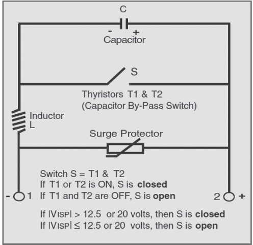
Figure 1: Simplified Circuit of an ISP
Functions of an ISP
Steady-State AC Operation
As seen in Figure 2 below, under normal operating conditions, when AC voltage is applied to the ISP, current flows through the inductor (L) and capacitor (C), supporting continuous conduction up to the selected steady-state AC current rating. The switch (S) and surge protection circuit remain open, and no current flows through them.
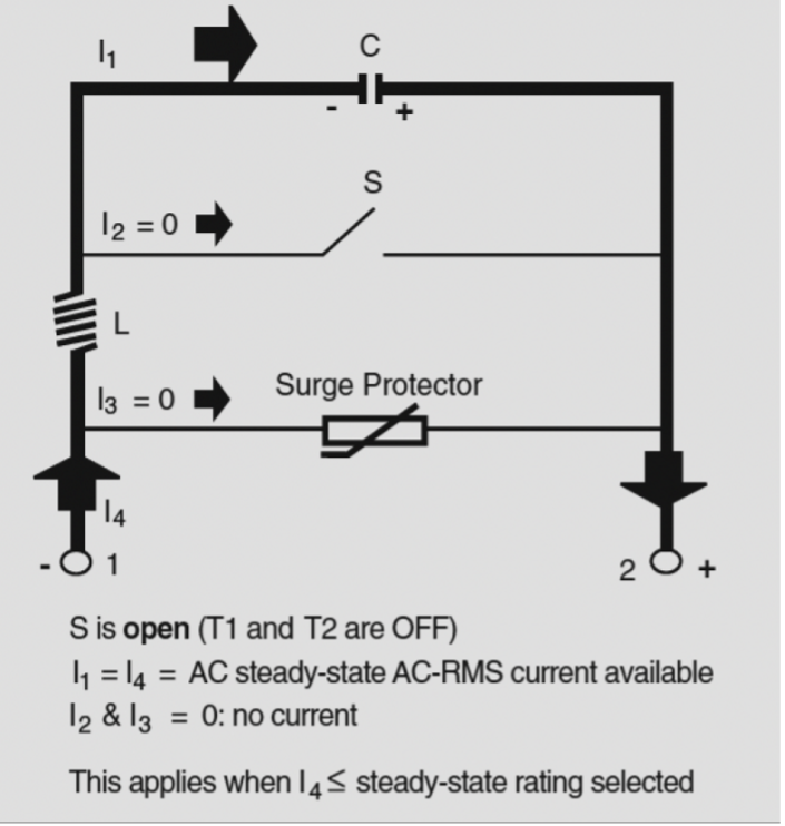
Figure 2: Steady-State AC Current Flow
AC fault current operation
The ISP is designed to withstand currents above its steady-state AC current rating, which means that during AC faults, it is protected against failure, however it no longer blocks DC. Whenever the device operates beyond its steady-state AC current limit or the DC voltage exceeds the switching threshold, a red indicator on the ISP cover flashes intermittently as a warning.
As shown in Figure 3, during an AC fault, the predominant current flow path moves through switch S1 (S) with minimal current flow through the capacitor (C). During this time, the capacitor (C) is protected from excessive current and voltage. There is no current flow through the surge protection path.
Dairyland ISPs are rated for 35kA, 68kA or 118kA, 1 cycle at 60Hz. Some older models remain in operation as well in 7kA and 24kA ratings.
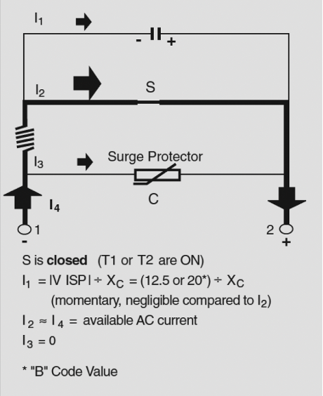
Figure 3: Current Path During AC Faults
Lightning and transient event operation
Under lightning (or switching transient) surge conditions, where the input current has a very fast rise time, the conduction path through the ISP is different than for AC conditions.
Please note Figure 4 below. When the ISP is exposed to a lightning surge, the voltage developed across the inductor (L) instantly rises to a value that places the surge protector (metal oxide varistor) into conduction, enabling the surge protector to carry the bulk of the current. Since the peak voltage across the thyristor also rapidly exceeds the threshold level, switch S is also put into conduction. However, the impedance of the current path through the thyristor is now much higher because the inductor is in series with this path. The impedance of the inductor allows only a small fraction of the surge current through the ISP to be carried by the thyristors, thereby preventing failure of the thyristors due to excessive rate of change of current. Most of the current will travel along the lower impedance path through the surge protector.
ISPs are rated for 75kA (standard) or 100kA (optional) 8x20ms waveform.

Figure 4: Current Path During Lightning Faults
Testing an ISP in-circuit
This test is completed with the device connected in-circuit — no terminal disconnections needed. Please note: this test only checks for internal shorts and not logic control circuit functions.
Refer to and follow company safety procedures prior to testing.
Equipment Required
- A multimeter with AC/DC amperes, volts, ohms.
- A clamp-on AC/DC ammeter
The ISP should be completely silent (noise-free). If an audible clicking sound is heard, the ISP is being subject to an AC current that is above its rating for the DC voltage applied. This sound is caused by a magnetic effect of certain solid-state components and is not any form of electrical arcing. In addition, a red indicator on the cover of the ISP will flash intermittently.
To verify that the ISP is functioning properly, first measure the AC voltage across the terminals using the DMM. Second, measure the AC current flowing through the negative terminal. Finally, calculate the impedance, Vac/Iac. These values should be approximately equal. Refer to the impedance table in this article and the nameplate of the ISP to determine the correct value to compare to.
Example1:
- Vac measured across terminals = 1V
- Iac measured with clamp-on = 10A
- Impedance Calculated = 1V / 10A = 0.1Ω
- For ISP with 90A rating, Published Impedance = 0.09Ω
- Values agree = Unit passes
Example 2:
- Vac measured across terminals = 0.1V
- Iac measured with clamp-on = 10A
- Impedance Calculated = 0.1V / 10A = 0.01 Ω
- For ISP with 90A rating, Published Impedance = 0.09Ω
- Values disagree = Unit fails test
- Unit is actively conducting or failed shorted.
- LED flashing if conducting (if present)
Testing with ISP Tester
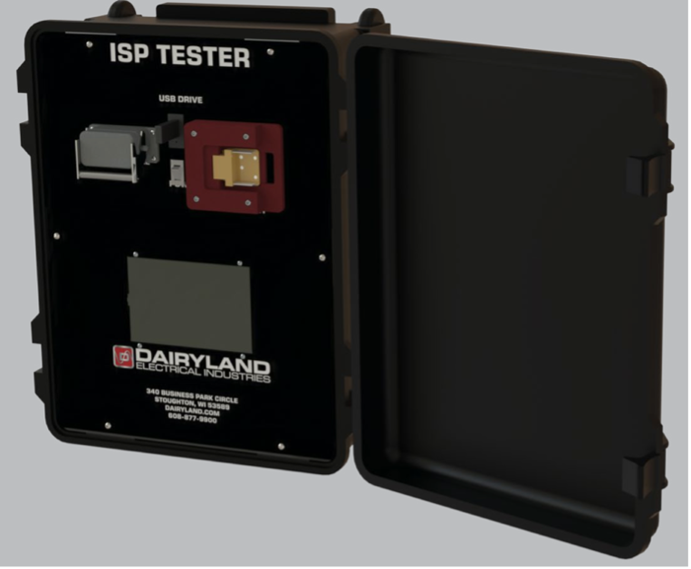
Figure 5: ISP Tester
The ISP Tester is an automated test device for performing in-circuit analysis of an ISP. The ISP is typically connected between the casing of a power utility pipe-type transmission cable system and the substation grounding system. Performing the functions of DC isolation and AC grounding for the transmission casing/sheath, an ISP is not easily removed from the system for the purpose of testing, therefore the ISP Tester performs an important role in analyzing an in-service ISP to determine its health.
The ISP Tester automatically evaluates the ISPs as-found condition and applies simulated AC fault signals to verify proper operation. It confirms that the ISP transitions into the low-impedance (ON) state under fault conditions, then reliably returns to its normal mode, blocking DC (from stray sources or cathodic protection systems) while allowing induced or coupled AC to pass to ground.
The ISP tester is initially configured via a simple touch panel interface. Following configuration, an automated test sequence is initiated by the operator. During the automated portion of the testing, the ISP is subjected to a multi-step test sequence controlled entirely by an on-board microprocessor. The sequence consists of various observational phases followed by two injections of a high current, short duration pulse which creates a temporary “fault” condition. During the test, the ISP is observed to verify that it properly triggers at either the 12.5V or 20V settings as initially selected on the touch panel and that the ISP properly recovers from a triggered condition. The brief high energy pulse causes the ISP to trigger only for a matter of several milliseconds, and a shorting system is applied to the external terminals to limit any influence on the external system. Operators of the ISP Tester should avoid contact with the exposed terminals of the ISP under test. Once initiated, the full test sequence requires approximately three to five minutes to complete. At the conclusion of the automated test sequence, informational data is combined with the actual test results and logged to a USB data drive.
If the ISP tester detects a problem during testing it will report the results in the home screen status box and abort any additional testing. There are fourteen possible failures and three successful results reported to the operator.
The ISP tester is available for purchase or rental. Please contact Dairyland for additional information.
Additional information may be found in the ISP’s technical literature, installation instructions and application guide. If you have any questions on the operation or testing of ISP’s, please contact Dairyland’s Technical Support team for guidance.
ISP Frequently Asked Questions
Frequently Asked Questions about Dairyland’s ISP
Dairyland’s ISP is the original solid-state AC conducting/DC blocking device designed for the corrosion prevention industry and features the most flexible and wide range of product ratings and applications available to the market. The ISP provides the widest range of features and ratings, including the highest levels of AC fault-handling capability – up to the highest typical transmission system faults making it the preferred product for power utility underground cable decoupling/bonding requirements. The following are some of the most frequently asked questions about ratings, logic board functionality, and installation.
To learn about the ISP’s different operating modes and how to test them, please see this article.
What is the leakage current of an ISP?
A relatively small DC leakage current is present during DC blocking, AC continuous operation. Figure 5 below provides an estimate of expected DC leakage current, which is dependent upon the DC voltage available at the terminals. We advise users to expect around 25mA per Volt.
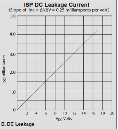
Figure 1: ISP DC Leakage Current
What is the importance of the logic circuit?
The most important component of the ISP is the logic-controlled circuit. This circuit determines exactly when the high current capacity thyristors should be turned “ON”. After a transient event, the circuit ensures the ISP returns to its normal operating mode, blocking DC while conducting AC. This prevents the thyristors from remaining in the ON state due to influence from a cathodic protection system or an external DC voltage source. The logic-controlled circuit, as with the entire ISP, is autonomous and does not require an auxiliary source of electrical power. It captures and stores the necessary power from any event that causes the voltage across, or the current through, the ISP terminals to reach the threshold level. Power is stored for a sufficient amount of time while the logic-controlled circuit deals with any foreseeable event.
The logic-controlled circuit includes a sub-circuit which provides a means for dissipating the stored inductive energy to prevent retriggering of the ISP. After this inductive energy is dissipated, the DC voltage will return to its normal steady-state value. The logic-controlled circuit then automatically goes dormant until the next triggering event occurs. The logic-controlled circuit differentiates between voltage rise caused by stored inductive energy, which should be safely dissipated, and external disturbances such as lightning surges or AC faults, where the ISP must trigger ON to protect itself and to limit voltage between its connected terminals.
Note on Revision 1 logic control circuit
The original logic-controlled circuit, designated as Revision 1, was introduced in the early 1990’s. This circuit revision does not protect an ISP from failure if the steady-state AC current is continually above rating. The Rev. 1 logic circuit does not include the following safety features:
- Prevention of capacitor overheating due to repeated retriggering if the ISP is operating above its steady-state ratings.
- Protection of the capacitor from excessive AC current that can occur below the absolute voltage threshold level of the ISP (applies when the 20V threshold level is selected).
- Provision for activating a flashing red warning indicator whenever the ISP is being repeatedly retriggered (due to application above steady-state rating).
ISPs with the original Rev. 1 logic control circuit were designed over 30 years ago, utilizing the most cutting-edge technology available at the time. Since that time, many technological advancements have been made. Dairyland now recommends that users of the older units consider upgrading to the newest Rev. 5 units.
Note on Revision 5 logic control circuit
Dairyland’s current ISP models utilize the latest Rev. 5 logic control circuit, which feature the following benefits:
- Inductive energy dissipation circuit that assures ISP remains OFF after fault event upgraded by 50% capacity for all models.
- Improved backup triggering of 26Vpeak if primary triggering fails.
- Prevention of capacitor overheating due to repeated retriggering if the ISP is operated above its steady-state ratings.
- Protection of the capacitor from excessive AC current that can occur below the absolute voltage threshold level of the ISP.
- 20V blocking voltage threshold standard.
- 90Arms steady-state AC current rating standard for models up to 68kA.
- 120Arms steady-state AC current rating for 118kA model.
What is the difference between 40 and 100 rating of logic control circuit?
These ratings indicate the maximum allowable DC current that can flow through the ISP during its conducting mode while still enabling the device to be automatically reset back to its normal mode after a fault condition. 40 is the standard rating, and it is capable of 40Adc. The 100 rating is optional, with capability of 100Adc.
Note that ISPs with Rev. 5 logic control circuit have 50% more capacity due to circuit improvements.
What is the impedance of an ISP?
For ISP units manufactured prior to 2020, the impedance value will vary depending on the steady-state current rating, as there were four options available. Impedance values are shown below:
| Steady-State ACrms Rating | mW (60Hz) | mW (50Hz) |
| 30A | 265 | 318 |
| 60A | 133 | 160 |
| 90A | 90 | 110 |
| 120A | 70 | 80 |
Table 1: Impedance values based on steady state current rating of an ISP
For ISP units manufactured in 2020 or later, only the 90A and 120A steady-state current ratings are available. The 90A and 120A impedance values shown above apply.
What is the difference in model numbers prior to 2020 and post-2020?
The ISP model number was streamlined in early 2020 for easier specification. Prior to 2020, there were numerous options that led to many variations of ISPs. The changes affected the steady-state current ratings, tamper-proof screws, and blocking voltage threshold.
The steady-state current ratings went from four options (30-120Arms) to only two options (90Arms or 120Arms), the blocking voltage threshold changed from two options (12.5V or 20V) to just the 20V option and finally, tamper-proof screws on the enclosure cover were made standard on all ISPs.
What is the purpose of the LED light?
The red LED indicator will flash approximately once per second if the DC voltage is above the voltage blocking level (12.5V or 20V), or if the steady state AC current is above the steady state rating of the ISP model (30A, 60A, 90A or 120A). Under normal operating conditions this LED should always be off.
If either of the above conditions occur, there will be an audible “clicking” sound as the thyristors are being switched.
Can ISPs be connected in parallel?
Single ISP models 35kA and 68kA should not be connected in parallel to double the AC fault current rating capability. The primary concern is that the logic control circuits are not synchronized to trigger at the same time during fault events. One of the units will trigger while the other one will not, thus the unit that triggers will see the full fault event and likely causing the ISP to fail.
For applications that require higher AC fault current capabilities, Dairyland recommends our highest rated ISP, the 118kA. This unit essentially has two single 68kA ISPs connected in parallel at the terminals and the logic controls circuits are synchronized together eliminating the issue mentioned above.
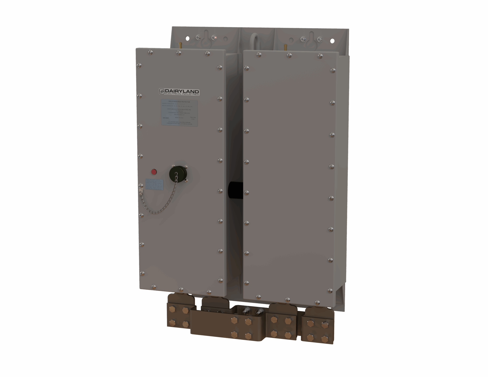
Dairyland’s ISP 118kA is recommended for applications that require higher AC fault current capabilities
Is an ISP listed for hazardous location use?
The ISP is a sealed, non-spark-producing device. This device meets the intent of ANSI/NFPA 70 (the U.S. National Electric Code) and CSA (Canadian Standards Association) requirements for Class I, Division 2 hazardous locations. The ISP has not been submitted for listing for hazardous locations because it is seldomly used in hazardous locations. If a listed device is required for hazardous locations, consider the PCR or PCRH, described in other literature sections.
Read more here about ISP’s different operating modes and how to test them.
If you have any questions regarding the information in this article, please feel free to contact us at techsupport@dairyland.com.
Q U I C K L I N K S
What is the difference between a Decoupler and an Over-Voltage Protector?
When do I need a Dairyland Decoupler?
How do I test a decoupler to know if it is working?
What is the difference between a PCR and an SSD?
Which products are rated for hazardous locations?
How do Dairyland decouplers compare to competing technologies?
What polarity should be used to connect a decoupler?
What is a “voltage threshold”? And how do I know that my decoupler has the correct voltage threshold for my application?
What should the spacing between decouplers be for AC Mitigation applications?
How do I spec a product for an insulated joint?
Dairyland technical support personnel work tirelessly to ensure all your needs are met when it comes to products, applications, and general support. Below, we have compiled a list of frequently asked questions regarding Dairyland decouplers and their various applications. This resource will also guide you to related articles in our Knowledge Base for further reading.
Dairyland decouplers keep workers and valuable assets safe from AC faults, lightning, and induced AC voltage, all while optimizing cathodic protection systems. We hold ourselves to a very high Always Rugged standard to ensure Dairyland products meet all critical performance requirements, provide fail-safe operation, and address hazardous location needs to guarantee longevity and safety.
Our tech support team is available during our normal business hours and can be reached via phone (608-877-9900) or email (TechSupport@dairyland.com).
What is the difference between a Decoupler and an Over-Voltage Protector?
Decouplers (PCR, PCRH, PCRX, and SSD) are commonly used to isolate cathodically protected structures from other equipment grounding systems, enhancing the cathodic protection system’s performance. They also perform a function of safely grounding induced AC, fault current and lightning. Over-Voltage Protectors (OVP and OVP2) provide the same DC isolation and protection from fault current and lightning but are not designed to address induced AC current.
Therefore, the first question to ask when selecting a Dairyland product family is whether there is (now or could be in the future) any induced AC voltage present. Induced AC commonly occurs on structures near overhead powerlines. If the answer is yes, or if you are unsure, you should select a decoupler to address any present or future issues with induced AC.
Additional Resources: “What Are Solid-state Decouplers and How Are They Used?” and “Over-Voltage Protection: The Critical Differences Between Spark Gaps and DC Decouplers.”
When do I need a Dairyland Decoupler?
The short answer is that a decoupler can be used for a variety of purposes and applications. Most frequently, they are installed when it is desirable to isolate DC current (CP current) while simultaneously grounding AC fault current and lightning current.
DC Decouplers are commonly used for applications such as:
- Isolating electric equipment from grounding systems, while still meeting electrical codes for safety
- Insulated joint over-voltage protection
- Connecting a cathodically protected pipeline to an AC mitigation system
- Tying a cathodically protected pipeline to a gradient control mat
- Grounding of power cable sheaths/casings to substation grounding systems
- Separating a facility with CP from power utility grounding systems beyond the transformer
Additional Resource: “AC Mitigation and Cathodic Protection: How Decouplers Make a Difference”
How do I test a decoupler to know if it is working?
A simple, indirect way to test a decoupler is through a standard pipe-to-soil reading. If your test shows acceptable CP levels, then the device is functioning properly. Decouplers are designed to block DC current, therefore acceptable cathodic protection readings reflect an operational Dairyland device.
For more detailed testing, please refer to our website’s tech articles: “Indirect Testing” & “Direct Testing.”
What is the difference between a PCR and an SSD?
PCRs and SSDs provide the same functions, and the main differences are in the ratings, package size, and cost.
- PCR AC fault ratings: 3.7 kA, 5 kA, 10 kA, and 15 kA.
- SSD AC fault ratings: 1.2 kA, 2.0 kA, 3.7 kA, and 5 kA.
Dairyland’s SSD was created as a more compact unit some years after the PCR. They share AC fault current capabilities, but the SSD was developed primarily for handling lower AC fault conditions. These units have identical hazardous location ratings, suitable for Division 2 and Zone 2 locations. PCR enclosures have either a NEMA 4X (IP66) rating or an optional NEMA 6P rating. SSDs enclosures have an IP68 rating (similar to NEMA 6P) that is rated for submersion up to two meters.
Additional Resource: “What if Decouplers Didn’t Exist?”
Which products are rated for hazardous locations?
PCR, PCRX, SSD, and OVP2 are all rated for use in areas with a Class I, Division 2 or Zone 2 classification. Class I, Division/Zone 2 units are suitable for most common applications, and these are Dairyland’s most frequently used devices.
PCRH and OVP are rated for use in areas with a Class I, Division 1 or Zone 1 classification. These units can still be used in any application with lesser requirements, such as Class 1, Division/Zone 2 installations.
Additional Resource: “Understanding Hazardous Locations”
How do Dairyland decouplers compare to competing technologies?
As a corrosion professional, your ideal applications keep your personnel safe and your system running efficiently. As an installer, you want tech that is easy to install and is maintenance-free. No matter your position, we know you are looking for solutions that address your various needs.
There are several devices on the market that attempt to resolve one or more of these concerns. However, maintenance needs, limited lifespans, and safety concerns all come attached to their price tags. Dairyland decouplers offer a solution to all your CP isolation and over-voltage protection needs. Because of their proven reliability, Dairyland’s solid-state decouplers are the smart choice over other DC isolation devices. Long-term, you will save maintenance labor and material costs by installing Dairyland devices. You will also mitigate risk to your equipment and personnel.
In addition to manufacturing industry-leading products, we pride ourselves on providing reliable technical support. Contact us any time.
Additional Resources: “Dairyland Decouplers vs. Competing Technologies” and “Dairyland OVP Devices vs. Competing Technologies”
What polarity should be used to connect a decoupler?
In general, the negative terminal connects to the more negative structure, and vice versa. Therefore, generally the + (Positive) goes to the ground connection and – (Negative) goes to the structure with CP. Across an insulated joint, where one side has CP and the other is grounded, connect negative to the protected side, and positive to ground. For an insulated joint with CP on both sides, select a symmetrical device, which is typically -2V/+2V, and then polarity is irrelevant.
Additional Resource: “Polarity Matters – Labels On Your Decoupler”
What is a “voltage threshold”? And how do I know that my decoupler has the correct voltage threshold for my application?
A decoupler’s voltage threshold is the voltage range supported between its terminals before direct current conduction. This is different from the industry measurement of “structure to soil” voltage, which is measured to a reference cell. The key value to measure is the difference between the two points a decoupler would be connected (pipe and ground) and compare that value to the negative threshold value.
For example, if a pipe-to-soil reading of -2V were obtained, and the reading from a grounding system to the same reference cell was -0.3V, then the decoupler connected between this pipe and grounding system would be exposed to -1.7V, which is the difference between the two readings. This assumes that the standard practice was used with decoupler negative terminal connected to the more negative structure (the pipeline) and positive to the grounding system. If the decoupler had a -3/+1V threshold, we compare the -1.7V reading to -3V value and find it acceptably below that threshold. Note that a -2/+2V threshold would have worked fine in this example as well. If the measured value were above the threshold, then the decoupler would be in full conduction and not block CP current. Standard Dairyland decoupler thresholds cover most pipeline situations.
A specific case that should be examined is where proximity to a rectifier results in elevated pipeline voltage that could approach the decoupler threshold and in that case one might consider the 3, 4, or 6 volt negative threshold to address this.
Additional Resources: “Understanding Voltage Threshold Ratings” & “Voltage Threshold Simulator”
What should the spacing between decouplers be for AC Mitigation applications?
Studies and testing should be conducted to accurately place Dairyland units for optimum AC mitigation and over voltage protection. Mitigation consultants are available to perform software modeling for optimal AC mitigation. Dairyland does not perform AC mitigation planning or studies. However, when we talk to mitigation designers regarding spacing, we have found that they often space these every ½ mile, presuming no pipeline or powerline changes in between that would cause a voltage spike. For example, whenever the pipeline or powerline change position relative to each other there will be a change in the magnetic field and a resulting voltage rise there, and a decoupler will be located near that change. Don’t forget other pipeline features such as insulated joints in the right-of-way that should be protected with a decoupler, as well as casings. AC mitigation design is a specialized field, and there are many factors that affect a design.
Additional Resource: “Decoupler Spacing for AC Mitigation Projects”
How do I spec a product for an insulated joint?
First, determine whether steady-state AC is present on either side of the joint.
- If AC is present, use PCR, PCRH, PCRX, or SSD.
- If AC is not present, use OVP or OVP2.
It is safer to assume that AC is present or could be in the future. Situations where AC is not likely are limited to airport fueling systems, and insulated joints interior to large facilities. Use caution, as AC induction on pipelines may require decouplers (SSD, PCR, PCRH) applied to a series set of insulated joints to mitigate AC to a station grounding system, only then allowing other insulated joints within a facility to utilize other Dairyland devices such as the OVP or OVP2. Due to complexity of stations, it is best to consult Dairyland staff for guidance.
Second, if the joint is in a Class I, Division 2 location, use models PCR, SSD, or OVP2 (most locations are Div 2/Zone 2). If the joint is in a Class I, Division 1 location, only use models PCRH or OVP.
Third, once the correct decoupler or over-voltage device is selected, choose the correct voltage threshold based on data (DC levels) collected from the pipeline. Typically, the standard ratings of -3/+1 or -2/+2 V are adequate. The -2/+2 (“symmetrical”) rating can be used where CP is present on both sides of a joint, or for CP present on one side of the joint only. The -3/+1 is generally only used where there is CP on one side of the joint and the other side is grounded. Remember to connect the negative terminal to the more negative, or cathodically protected, side.
Additional Resource: “Over-Voltage Protection: The Critical Differences Between Spark Gaps and DC Decouplers”
Bonus Additional Resources Regarding the MEGA Rule:
- “PHMSA Mega Rule Explained and How Dairyland Can Help You“
- “Understanding the Mega Rule: Accurate Close Interval Surveys“
- “Understanding the Mega Rule: Interference Mitigation“
- “Understanding the Mega Rule: RMV Installation Best Practices“
Should you have an eleventh or twelfth question, do not hesitate to contact our team at TechSupport@dairyland.com.
Dairyland technical experts are occasionally asked how decoupler leakage current may affect potential readings of pipelines with no CP current applied. This article is intended to help answer questions related to the effects of DC leakage current through decouplers and how native or depolarized potential surveys may be impacted.
DC Leakage Current
Dairyland decouplers have a high resistance to DC current flow. There are situations where some DC current flow, known as DC leakage current, may be witnessed especially during native or depolarized potential pipeline surveys. For example, there may be a situation where a brand-new pipeline is being checked for its baseline potential voltage (i.e. native potential) to establish limits for use in the 100mV shift criterion from NACE SP0169. In this case, there may be some influence on the pipeline from the grounding wire connected through a decoupler for AC mitigation. This will be further explained in the paragraphs below.
This leakage current is typically in the single to double digit milliampere range. Graphs are presented in the Technical Literature for the products, and an example is shown here for the PCR decoupler:

These graphs reveal that as the DC voltage difference across the two decoupler terminals increases, there will be an increase in leakage current. Similarly, as temperatures increase, there will be an increase in leakage current. For example, in the graph shown above, a PCR decoupler with 2 V-DC across its terminals at 20 deg C (68 deg F) will have approximately 0.3 mA of DC leakage current. Note that the 65 deg C (149 deg F) is a graph to illustrate the upper temperature limits of the PCR.
This small amount of DC leakage can sometimes be noticed during normal operations. For example, at a site with active AC mitigation, the amount of AC amperage flowing through the decoupler is often measured. Note that small amounts of DC amperage may also be measured through the decoupler. A DC ammeter with a high resolution would typically be needed to see the DC amperage flow values and they will normally be less than 2 milliamps, with acceptable values reaching up to 20 milliamps.
Native Potential Surveys
Native potential surveys are used to get the open circuit potential for a metal placed into a soil using a reference electrode, such as a copper-copper sulfate reference electrode (CSE). The native potential is often captured after the pipeline is installed and allowed to acclimate to the surrounding soil conditions. There is no cathodic protection applied before the survey takes place. Another method to gather this baseline metal potential is to perform a depolarized survey. This means that cathodic protection was applied to the buried metal system, but is subsequently disconnected and the pipe is allowed to depolarize and return to it’s native state.
However, during the native potential survey the pipeline may be influenced if it remains connected to a decoupler with a grounding wire or another CP circuit on the positive side of the decoupler. Leakage current may impact expected pipe-to-soil readings of the pipeline with no cathodic protection applied, due to the small amount of DC leakage through the decoupler. The type of connected system can have varying effects on the native potential values on the pipeline as described below:
- Copper Grounding Systems: With a copper grounding system, the native potential of the copper is naturally at a less negative value on the galvanic series scale compared to a steel pipeline. Note that there is a very small differential in voltage potential between copper and steel, so the leakage current is very low and likely will not be noticed on the pipeline native potential surveys. Therefore, even if the decoupler remains connected between the pipe and the copper ground, there will be minimal impact to the values read during a native potential survey.
- Zinc Grounding Systems: A zinc grounding system presents a different scenario to a native potential survey as compared to copper. Since zinc is more anodic to the steel, there can be elevated pipe potentials found on a steel pipeline due to DC leakage current through the decoupler if it remains connected to the zinc grounding. This can be especially pronounced with new pipeline installations since the coating will be in pristine condition, resulting in extremely low amounts of current from the zinc to elevate the pipe potentials.
- Other CP Systems: The cathodic protection levels of a decoupled CP system can similarly affect the native potentials of the surveyed pipeline. The CP system will influence the native potential readings similar to how the zinc grounding system would behave, by increasing the potentials of the surveyed pipeline.
As a best practice, during native potential surveys, Dairyland recommends disconnecting all decouplers between the pipeline and the grounding circuit, and at locations where CP systems are isolated, such as isolation flanges. This ensures that the native potential survey will not be influenced by decoupled grounding or CP systems.
Leakage Current Values for Various Decouplers
For reference, the following table is provided to clarify the DC leakage current for various decoupler models and fault ratings. Note that this table covers the SSD, PCR, PCRH and PCRX decouplers only. For other Dairyland products, please consult Tech Support.
| Product Name | Threshold | Fault Rating | Leakage Current Amperes |
| SSD | -2/+2 | 1.2 kA | <5mA |
| 2 kA | <5mA | ||
| 3.7 kA | <5mA | ||
| 5 kA | <5mA | ||
| SSD | -3/+1 | 1.2 kA | <5mA |
| 2 kA | <5mA | ||
| 3.7 kA | <5mA | ||
| 5 kA | <5mA | ||
| PCR, PCRH | -2/+2 | 3.7 kA | <5mA |
| 5 kA | <5mA | ||
| 10 kA | <10mA | ||
| 15 kA | <20mA | ||
| PCR, PCRH | -3/+1 | 3.7 kA | <5mA |
| 5 kA | <5mA | ||
| 10 kA | <5mA | ||
| 15 kA | <20mA | ||
| PCRX | -4.5/+3.5 | 5.0 kA | <5mA |
| 10 kA | <10mA | ||
| 15 kA | <20mA | ||
| PCRX | -5.5/+2.5 | 5.0 kA | <5mA |
| 10 kA | <10mA | ||
| 15 kA | <20mA |
In the world of oil and gas pipelines, decouplers play a critical role enabling safe and sustainable pipeline operation. In fact, decouplers perform an essential role in corrosion mitigation – ensuring safety, regulatory compliance, preventing costly damage and downtime for pipelines and related assets. They also provide shock protection to personnel and pipeline assets from safety hazards, caused by power line faults, electrical failure of equipment, and lightning strikes. The decoupler, however, is often misunderstood and its application under appreciated. Here we demystify decouplers and explain the vital role they play.
This article was originally published in World Pipelines, Volume 24, Number 11, November 2024.
This is the second article in our series designed to provide clarity amid the many new complexities surrounding the Mega Rule (read the first in the series). Corrosion control and repair criteria are central to Part 3 of the Mega Rule and here we focus on challenges around interference mitigation. Throughout this series, we also present solutions designed to help informed decision making and compliance.
The Mega Rule
To recap, the Mega Rule builds on and updates existing legislation designed to reinforce a risk management approach to the safety of natural gas transmission pipelines, natural gas distribution pipelines, and hazardous liquid transmission pipelines. Its third and final part became effective in February of 2023 with a compliance deadline of February 2024. It clarifies integrity management regulations from corrosion control requirements and repair criteria to post extreme weather inspection and applies to onshore gas pipeline infrastructure spanning HCA, and non-HCA.
The Mega Rule updates are challenging but Dairyland’s expertise and technologies are proven to mitigate interference, helping to deliver compliance, ensure safety and create competitive edge.

Background
For a range of logistical, land access and environmental purposes, it is a global norm for pipelines to share Right-of-Way (ROW) with high-voltage power lines creating a network of utility corridors. In these multi-purpose routes that often span long distances, AC corrosion risk is increased due to undesirable AC interference while also raising shock hazard risk to personnel who come in contact with the pipeline or appurtenances.
Challenge #2: Interference Mitigation
To understand the extent of corrosion and pipeline integrity, interference surveys are essential. Pipeline infrastructure and associated equipment have voltage limits and mitigative measures are required to reduce corrosion risk, lessen the risk to personnel, prevent costly damage and downtime.
To ensure compliance with the new regulations, interference surveys are undertaken when periodic monitoring indicates an increase in stray current, or new stray current sources are introduced. Sources of stray current can include co-located pipelines, structures, or high voltage alternating current (HVAC) or DC power lines (including from additional generation), a voltage up-rating, additional lines, new or enlarged power substations, new pipelines, or other structures. If the interference current is greater than or equal to 100 amps per meter squared a remedial action plan must be developed and implemented within a rule-stipulated time frame.
The risk of interference is heightened through the transferal of electrical energy onto a pipeline in multiple ways. Apart from the expected interference on multi-purpose routes, faults beyond the control of the pipeline operator, including lightning strikes, can take their toll on asset integrity. Furthermore, damage to overhead transmission systems from extreme weather or technical failures can increase the risk of line-to-ground damage. All these risks, and many more besides, must be mitigated against.
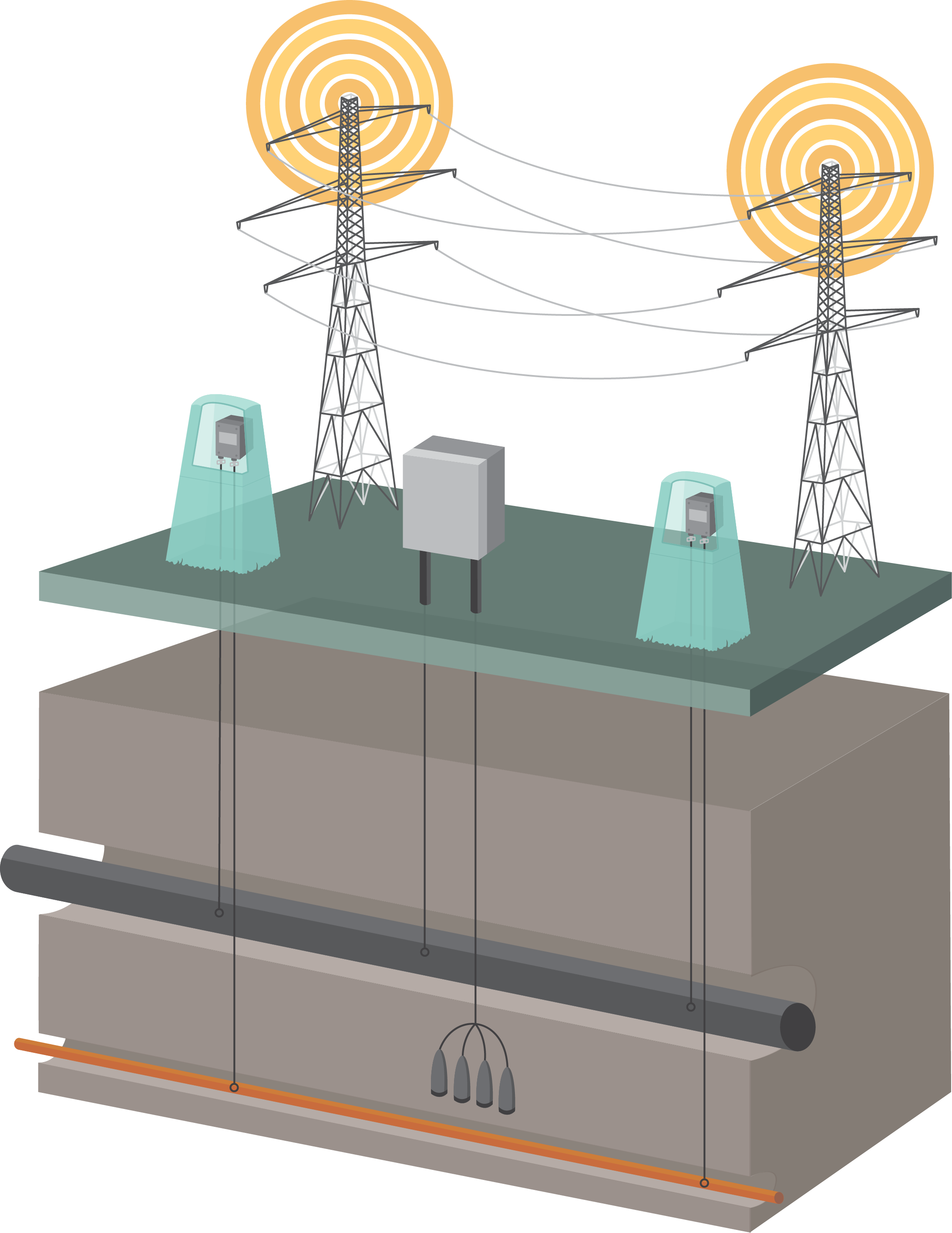
Solution #2: Interference Mitigation
Engineered interference mitigation systems can reduce AC voltages to an acceptable level, significantly reducing cost implications and improving safety over the operational lifespan of pipeline infrastructure. Dairyland products are proven, critical components of successful AC interference mitigation systems globally. Our decouplers such as the SSD, PCR, and PCRX, provide an effective grounding path that mitigates induced AC, while simultaneously maintaining DC isolation. Indeed, effectively utilizing decouplers in AC mitigation applications will help to minimize voltage differences to safe levels for both personnel and equipment when grounding is required to address safety and equipment concerns and isolation is required to maintain an effective cathodic protection (CP) system. Dairyland decouplers are appropriately rated to manage over-voltage conditions while simultaneously providing CP system isolation, protecting the integrity of your CP, maintaining a low impedance path to earth for AC and lightning, protecting your personnel and equipment.
With the Mega Rule impacting approximately 300,000 miles of existing onshore natural gas pipeline, and almost 20,000 miles of planned pipeline in the US, extending the life of these assets and building them in compliance with the regulations will require innovative technology and solutions.
Dairyland is here to help you make decisions on how our solutions can be applied to achieve Mega Rule compliance. We pride ourselves on being a reliable resource for complete technical guidance and our technical support staff is ready to support you in a variety of ways – even if you don’t end up needing our products.
Mega Rule Article 1: Accurate Close Interval Surveys
Mega Rule Article 3: RMV Installation Best Practices